
 USD
USD


Filter
ブランド
Featured
値段
タグ
シンセ・モジュール
The Eurorack modular synth format is one of the most exciting areas of music technology. Pioneered by Doepfer, there are now hundreds of brands offering compatible modules of all varieties. You can combine your choice of the best oscillators, filters and much more in order to create a unique, bespoke synth setup which perfectly suits your needs.
Eurorack modules offer the biggest range of options you can imagine, from basic analogue modules which replicate the sound of classic vintage synths, through to digital modules which allow you to explore completely new approaches to making music.
Whether you’re a beginner or a more experienced modular head, you can take your pick of the best modules from leading brands including Mutable Instruments and ALM Busy Circuits.
Our range also includes accessories, cases, patch cables and much more, allowing you to build and customise your perfect modular synth setup.
こんな商品も購入されています...
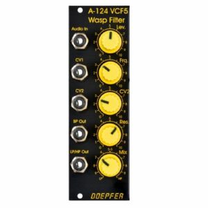
Doepfer A-124 VCF5 Wasp Filter 12dB Multimode Filter Module (special edition, black/yellow) (filter synth module)
Cat: 671564 Rel: 29 Nov 17
12dB multi-mode filter with unique classic circuitry, based on the filter from the 70s EDP Wasp synth
Notes: Module A-124 is a special 12dB multimode filter using the "strange" filter circuit of the "EDP Wasp" (an analog synthesizer with black/yellow case built end of the seventies, manufactured by the UK company "Electronic Dream Plant" with Chris Huggett und Adrian Wagner). This design "abuses" digital inverters as analog operational amplifiers leading to distortions and other "dirty" effects that generate the specific sound of this filter. The filter is equipped with a band pass output and a combined low/notch/high pass output. For this output a control knob defines the relation between low and high pass signal. If both signals appear at the same level (i.e. middle position of the Mix knob) one obtains a notch filter. Otherwise the low or high pass signal predominates. The module does not feature self-oscillation in contrast to most of the other filters of the A-100 system.
Inputs: Audio In, CV In (2x)
Outputs: Bandpass Out, Low/Highpass Mix-Out
Controls: Audio and CV attenuator, Frequency, Resonance, LP/HP Mix
The function and operation of this module is very similar to the module SEM VCF A-106-5. But the sound of both filters is very different! The only functional difference is the position of the sockets and controls, and the function of the controls CV2 (A-124: normal attenuator, A-106-5: polarizer).
- 3U Eurorack module, 8HP wide, 45mm deep
- Current draw 30mA
… Read moreInputs: Audio In, CV In (2x)
Outputs: Bandpass Out, Low/Highpass Mix-Out
Controls: Audio and CV attenuator, Frequency, Resonance, LP/HP Mix
The function and operation of this module is very similar to the module SEM VCF A-106-5. But the sound of both filters is very different! The only functional difference is the position of the sockets and controls, and the function of the controls CV2 (A-124: normal attenuator, A-106-5: polarizer).
- 3U Eurorack module, 8HP wide, 45mm deep
- Current draw 30mA
4 in stock $90.97
Click for better price!
or call +44 20 7424 1960
quote 671564
quote 671564
こんな商品も購入されています...
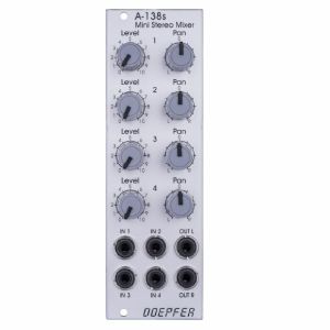
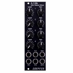
Doepfer A-138s Mini Stereo Mixer Module (silver) (mixer synth module)
Cat: 671589 Rel: 29 Nov 17
Four-channel stereo mixer - 8HP
Notes: A-138s is a simple but useful 4-in-2 mixing tool. It has four inputs available. Each input is equipped with an attenuator (Level) and a panning control that is used to distribute the signal to the left and right output. Beyond stereo mixing it is equally suited to create variable parallel routings. For example: Any of the four inputs may be routed in variable intensity to feed two filters.
You may regard the A-138s as a smaller version of the A-138m Matrix Mixer.
Inputs and outputs are DC coupled, i.e. the module can be used for the mixing of control signals too.
- 3U Eurorack module, 8 HP wide, 30 mm in depth
- Power consumption: 10 mA at +12 V and 10 mA at -12 V
… Read moreYou may regard the A-138s as a smaller version of the A-138m Matrix Mixer.
Inputs and outputs are DC coupled, i.e. the module can be used for the mixing of control signals too.
- 3U Eurorack module, 8 HP wide, 30 mm in depth
- Power consumption: 10 mA at +12 V and 10 mA at -12 V
3 in stock $85.42
Click for better price!
or call +44 20 7424 1960
quote 671589
quote 671589
こんな商品も購入されています...
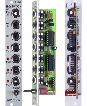
Doepfer A-151 Sequential Switch v2 Module (silver) (switch synth module)
Cat: 577792 Rel: 06 Jun 19
Quad sequential switch module - 4HP
Notes: Module A-151 (Quad Sequential Switch) is like an electronic four-position rotary switch.
It includes trigger and reset inputs, four in / outputs, and a common out / input. Each time a pulse is received at the trigger input socket, the common out / input is connected to the next in / output. After the fourth in / output, the next trigger makes it step back to the first again, and so on. A positive pulse at the reset input switches the out / input immediately back to the first in / output.
Voltages in the range -12V...+12V at the O/I resp. I/O sockets can be processed by the module (not only control voltages but also gate, trigger or clock signals provided that they are in the -12V...+12V range).
By means of a toggle switch the number of steps can be limited to 2, 3 or 4.
Four LEDs indicate the active in / output (ie. the on that is connected to the out / input at any particular time).
For more detailed information please look at the English user's manual: A151_man.pdf.
Similar modules:
A-150-1 Dual Voltage Controlled Switch
A-150-8 Octal Manual/Voltage Controlled Programmable Switches
A-152 Voltage Addressed Track&Hold / Switch (Multiplexer) / Digital Outputs
Technical notes:
To protect the electronic switches in case of an unsuitable patch (e.g. connection of two outputs) a 1k protection resistor is inserted into the O/I line. If control voltages used for VCOs are switched this may cause a small voltage drop and lead to undesired audible detuning. For this application we recommend to insert a CV buffer between A-151 and the VCO(s), e.g. the modules A-180-3, A-180-4 or the Precision Adder A-185-2. Integrating the buffer into the module A-151 is not possible because this would ruin the bidirectionality of the switches.
For modules manufactured before spring 2005 the voltage range at the in/outputs was limited to -8V...+8V. From spring 2005 the revised version of the module was available. With an additional switch the number of steps can be set to 2, 3 or 4 (thanks to Peter Grenader for this idea). Moreover the revised module allows to process voltages in the full A-100 voltage range (i.e. -12V...+12V). The limitation to -8V...+8V is no longer valid. The A-100 DIY page describes how to install this additional switch for the old version of A-151.
Width: 4 HP / 20.0 mm
Depth: 35 mm (measured from the rear side of the front panel)
Current: +20mA (+12V) / -10mA (-12V)
… Read moreIt includes trigger and reset inputs, four in / outputs, and a common out / input. Each time a pulse is received at the trigger input socket, the common out / input is connected to the next in / output. After the fourth in / output, the next trigger makes it step back to the first again, and so on. A positive pulse at the reset input switches the out / input immediately back to the first in / output.
Voltages in the range -12V...+12V at the O/I resp. I/O sockets can be processed by the module (not only control voltages but also gate, trigger or clock signals provided that they are in the -12V...+12V range).
By means of a toggle switch the number of steps can be limited to 2, 3 or 4.
Four LEDs indicate the active in / output (ie. the on that is connected to the out / input at any particular time).
For more detailed information please look at the English user's manual: A151_man.pdf.
Similar modules:
A-150-1 Dual Voltage Controlled Switch
A-150-8 Octal Manual/Voltage Controlled Programmable Switches
A-152 Voltage Addressed Track&Hold / Switch (Multiplexer) / Digital Outputs
Technical notes:
To protect the electronic switches in case of an unsuitable patch (e.g. connection of two outputs) a 1k protection resistor is inserted into the O/I line. If control voltages used for VCOs are switched this may cause a small voltage drop and lead to undesired audible detuning. For this application we recommend to insert a CV buffer between A-151 and the VCO(s), e.g. the modules A-180-3, A-180-4 or the Precision Adder A-185-2. Integrating the buffer into the module A-151 is not possible because this would ruin the bidirectionality of the switches.
For modules manufactured before spring 2005 the voltage range at the in/outputs was limited to -8V...+8V. From spring 2005 the revised version of the module was available. With an additional switch the number of steps can be set to 2, 3 or 4 (thanks to Peter Grenader for this idea). Moreover the revised module allows to process voltages in the full A-100 voltage range (i.e. -12V...+12V). The limitation to -8V...+8V is no longer valid. The A-100 DIY page describes how to install this additional switch for the old version of A-151.
Width: 4 HP / 20.0 mm
Depth: 35 mm (measured from the rear side of the front panel)
Current: +20mA (+12V) / -10mA (-12V)
1 in stock $56.97
こんな商品も購入されています...
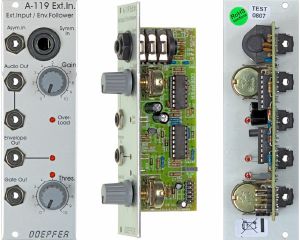
Doepfer A-119 External Input Envelope Follower Module (silver) (external/envelope follower/preamp/controller/comparator synth module)
Cat: 577771 Rel: 29 Nov 17
Envelope follower & pre-amplifier for microphone/line-signals - 8HP
Notes: Module A-119 (External Input / Envelope Follower) is designed to allow external audio signals to be integrated into the System A-100. It comprises a pre-amp, envelope follower, and comparator.
The pre-amp has two inputs: an unbalanced input for line level signals, with a gain factor of from 0 to 20, and a balanced input with a gain factor of from 0 to 500, for insertion of low level signals, for instance from a microphone or electric guitar.
The Envelope Follower reads the signal level of the input, and puts out a proportional voltage as an envelope at its own output.
The comparator generates a gate signal whenever the input goes above an adjustable trigger threshold.
Three LED's help you keep track of overload, the envelope, and the gate signal.
… Read moreThe pre-amp has two inputs: an unbalanced input for line level signals, with a gain factor of from 0 to 20, and a balanced input with a gain factor of from 0 to 500, for insertion of low level signals, for instance from a microphone or electric guitar.
The Envelope Follower reads the signal level of the input, and puts out a proportional voltage as an envelope at its own output.
The comparator generates a gate signal whenever the input goes above an adjustable trigger threshold.
Three LED's help you keep track of overload, the envelope, and the gate signal.
1 in stock $79.86
Click for better price!
or call +44 20 7424 1960
quote 577771
quote 577771
こんな商品も購入されています...
Doepfer A-138n Narrow Mixer Module (silver, slim line series) (mixer synth module)
Cat: 731947 Rel: 10 Jun 19
4-channel mixer module - 4HP
Notes: Module A-138n is a simple four channel mixer, which can be used with either control voltages or audio signals. Each of the four inputs has an attenuator available. The output is twice available (two sockets, hard-wired like a multiple).
The module is the slim version of module A-138a and offers nearly the same features. But the distances between the controls are smaller and rubberized small-sized knobs are used. In return the front panel has 4 HP only which is half the width of the A-138a. The module is primarily planned for applications where only limited space is available. The only functional difference compared to the A-138a is the missing attenuator for the (dual) output.
Width: 4HP / 20.0 mm
Depth: 30 mm (measured from the rear side of the front panel)
Current: +10mA (+12V) / -10mA (-12V)
… Read moreThe module is the slim version of module A-138a and offers nearly the same features. But the distances between the controls are smaller and rubberized small-sized knobs are used. In return the front panel has 4 HP only which is half the width of the A-138a. The module is primarily planned for applications where only limited space is available. The only functional difference compared to the A-138a is the missing attenuator for the (dual) output.
Width: 4HP / 20.0 mm
Depth: 30 mm (measured from the rear side of the front panel)
Current: +10mA (+12V) / -10mA (-12V)
4 in stock $58.18
こんな商品も購入されています...
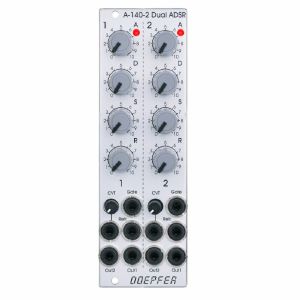
Doepfer A-140-2 Dual Micro ADSR Module (silver) (envelope generator synth module)
Cat: 684450 Rel: 18 Jul 18
Dual ADSR envelope generator - 8HP
Notes: Module A-140-2 contains two ADSR type envelope generators behind a front panel with 8 HP only.
Each ADSR provides these controls and in/outputs:
- LED (displays the envelope output)
- A: manual Attack control
- D: manual Decay control
- S: manual Sustain control
- R: manual Release control
- Gate Input
- Retrigger Input
- CVT Input with attenuator (CVT = CV Time)
- Envelope Output 1
- Envelope Output 2
The output voltage range for each envelope is 0 - 10V. The time range of Attack/Decay/Release is about 1ms to 30s.
By means of internal jumpers one can select which time parameters are controlled by the CVT input (e.g. D only or D+R or A+D+R) and in which direction (i.e. if an increasing CVT shortens or stretches the time parameter in question).
Socket CVT can be normalled to an internal fixed voltage (i.e. the switching contact is connected to an internal fixed voltage). That way it's possible to change all time parameters simultaneously by means of the CVT control.
Another jumper is used to set output 2 to normal or inverted envelope.
And another jumper is used for the normalling of Gate 2 to Gate 1 (i.e. ADSR#2 is also triggered by Gate 1).
Two more jumpers are used for the optional bus access to the gate signal of the bus for each ADSR. Changing the positions of the mentioned jumpers allows to modify the factory settings.
… Read moreEach ADSR provides these controls and in/outputs:
- LED (displays the envelope output)
- A: manual Attack control
- D: manual Decay control
- S: manual Sustain control
- R: manual Release control
- Gate Input
- Retrigger Input
- CVT Input with attenuator (CVT = CV Time)
- Envelope Output 1
- Envelope Output 2
The output voltage range for each envelope is 0 - 10V. The time range of Attack/Decay/Release is about 1ms to 30s.
By means of internal jumpers one can select which time parameters are controlled by the CVT input (e.g. D only or D+R or A+D+R) and in which direction (i.e. if an increasing CVT shortens or stretches the time parameter in question).
Socket CVT can be normalled to an internal fixed voltage (i.e. the switching contact is connected to an internal fixed voltage). That way it's possible to change all time parameters simultaneously by means of the CVT control.
Another jumper is used to set output 2 to normal or inverted envelope.
And another jumper is used for the normalling of Gate 2 to Gate 1 (i.e. ADSR#2 is also triggered by Gate 1).
Two more jumpers are used for the optional bus access to the gate signal of the bus for each ADSR. Changing the positions of the mentioned jumpers allows to modify the factory settings.
1 in stock $151.89
こんな商品も購入されています...
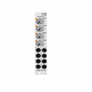
Doepfer A-145-4 LFOs Quad Low Frequency Oscillator Slim Line Module (silver) (LFO synth module)
Cat: 731949 Rel: 10 Jun 19
Quad low frequency oscillator - 4HP
Notes: Module A-145-4 is a simple quad LFO (Low Frequency Oscillator). Not a very "exciting" module, just a bread-and-butter device and a simple demon for work. Virtually in every modular system several LFOs are required for modulation purposes. The module contains four simple LFOs with the waveforms triangle and rectangle. A dual colour LED (red = positive / yellow = negative output voltage) indicates the triangle output of each LFO. The frequency range can be chosen for each LFO individually by means of a jumper between about 50 Hz ... 0.04 Hz (about 20 seconds, jumper removed) and about 2Hz ... 0.002 (about 8 minutes, jumper installed).
The module can be treated as a slimmed version of the quad LFO A-143-3 as it has similar features available. But the distances between the controls are smaller and rubberized small-sized knobs are used. In return the front panel has 4 HP only which is less than one third of the A-143-3. The module is primarily planned for applications where only limited space is available. The functional difference compared to the A-143-3 are the missing sawtooth outputs and frequency range switches.
… Read moreThe module can be treated as a slimmed version of the quad LFO A-143-3 as it has similar features available. But the distances between the controls are smaller and rubberized small-sized knobs are used. In return the front panel has 4 HP only which is less than one third of the A-143-3. The module is primarily planned for applications where only limited space is available. The functional difference compared to the A-143-3 are the missing sawtooth outputs and frequency range switches.
1 in stock $83.06
こんな商品も購入されています...
Doepfer A-130-2 Dual Linear/Exponential VCA Slim Line Series Module (dual/stereo/VCA synth module)
Cat: 731940 Rel: 11 Jun 19
Compact two-channel VCA - 4HP
Notes: Module A-130-2 is the slim version of module A-132-3 and offers essentially the same features. But the distances between the controls are smaller and rubberized small-sized knobs are used. In return the front panel has 4 HP only which is half the width of the A-132-3. The module is primarily planned for applications where only limited space is available.
The module is composed of two identical voltage controlled amplifiers (VCA). Each VCA has a manual gain control (also named Initial Gain) and a control voltage input with attenuator. The character of the control scale can be switched to linear or exponential. All inputs and outputs are DC coupled. Consequently the VCAs can be used to process both audio and control voltages (e.g. for voltage control of the level of LFO or envelope signals). The signal input has no attenuator available but is capable to process up to 16Vpp signals (i.e. -8V...+8V) without distortion. For the processing of higher levels an external attenuator (e.g. A-183-1) is recommended.
The amplification range is 0...1. Even with a higher external control voltage the amplification remains at 1 (kind of "amplification clipping" at 1).
Controls (for each of both units):
- Gain: manual gain control (Initial Gain) in the range 0...1
- CV: attenuator for the CV input
- Lin/Exp: switches the VCA characteristic to linear or exponential, in center position the VCA is off (mute function)
Inputs and outputs (for each of both units):
- CV: control voltage input, min. +5V required for max. amplification (1) with CV control fully CW and Gain fully CCW
- In: signal input, max. 16Vpp (+8V...-8V) without distortion
- Out: signal output
… Read moreThe module is composed of two identical voltage controlled amplifiers (VCA). Each VCA has a manual gain control (also named Initial Gain) and a control voltage input with attenuator. The character of the control scale can be switched to linear or exponential. All inputs and outputs are DC coupled. Consequently the VCAs can be used to process both audio and control voltages (e.g. for voltage control of the level of LFO or envelope signals). The signal input has no attenuator available but is capable to process up to 16Vpp signals (i.e. -8V...+8V) without distortion. For the processing of higher levels an external attenuator (e.g. A-183-1) is recommended.
The amplification range is 0...1. Even with a higher external control voltage the amplification remains at 1 (kind of "amplification clipping" at 1).
Controls (for each of both units):
- Gain: manual gain control (Initial Gain) in the range 0...1
- CV: attenuator for the CV input
- Lin/Exp: switches the VCA characteristic to linear or exponential, in center position the VCA is off (mute function)
Inputs and outputs (for each of both units):
- CV: control voltage input, min. +5V required for max. amplification (1) with CV control fully CW and Gain fully CCW
- In: signal input, max. 16Vpp (+8V...-8V) without distortion
- Out: signal output
3 in stock $89.04
Click for better price!
or call +44 20 7424 1960
quote 731940
quote 731940
こんな商品も購入されています...
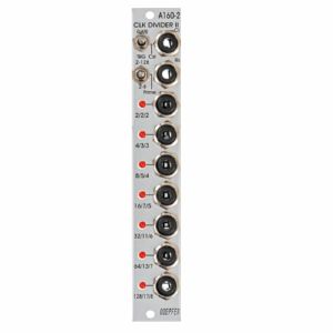
Doepfer A-160-2 Clock/Trigger Divider II Module (silver) (clock modulator/frequency divider synth module)
Cat: 671576 Rel: 29 Nov 17
Enhanced clock divider with multiple dividing factors - 4HP
Notes: Module A-160-2 is an enhanced version of the standard clock divider A-160. The module is a frequency divider for clock/trigger/gate signals, designed to be a source of lower frequencies, particularly for rhythm uses. The Clock input will take any digital signal from, eg. LFO, MIDI sync, or the gate from a MIDI-CV interface. At the outputs, you have access to three sets of seven different sub-divided clock signals, from half the clock frequency down to 1/128. The low/high levels of the output signals are 0V and about +10V.
The A-160-2 also has a reset input. Whenever a reset signal is sensed, all outputs are set to certain levels which depend upon the selected mode.
These are the most important features of the module:
Three different sets of dividing factors, selected by a three-position switch at the front panel:
- Power of two: 2, 4, 8, 16, 32, 64, 128
- Prime numbers: 2, 3, 5, 7, 11, 13, 17
- Integer: 2, 3, 4, 5, 6, 7, 8
Two output modes, selected by a two-position switch at the front panel:
- Gate mode: outputs act like the outputs of typical binary dividers
- Trigger mode: in this mode the outputs are AND-wired with the clock signal (i.e. the clock pulsewidth affects the pulsewidth of the outputs)
- Clock edge type selected by a jumper on the pc board:
- Positive: the rising edge of the clock signal triggers the state change of the outputs
- Negative: the falling edge of the clock signal triggers the state change of the outputs
Reset behaviour by two jumpers on the pc board:
- Level triggered: the level at the Reset input triggers the Reset
- Edge triggered: the edge of the signal at the Reset input triggers the Reset
- Positive: a high level (> 2.5V) or the rising edge at the Reset input triggers the Reset
- Negative: a low level (< 1 V) or the falling edge at the Reset input triggers the Reset
Output polarity selected by a jumper on the pc board:
- Positive: non-inverted outputs
- Negative: all seven outputs are inverted
Width: 4HP / 20mm
Depth: 35mm (Measured from the rear side of the front panel)
Current: +12V: +50mA, -12V: -0mA
… Read moreThe A-160-2 also has a reset input. Whenever a reset signal is sensed, all outputs are set to certain levels which depend upon the selected mode.
These are the most important features of the module:
Three different sets of dividing factors, selected by a three-position switch at the front panel:
- Power of two: 2, 4, 8, 16, 32, 64, 128
- Prime numbers: 2, 3, 5, 7, 11, 13, 17
- Integer: 2, 3, 4, 5, 6, 7, 8
Two output modes, selected by a two-position switch at the front panel:
- Gate mode: outputs act like the outputs of typical binary dividers
- Trigger mode: in this mode the outputs are AND-wired with the clock signal (i.e. the clock pulsewidth affects the pulsewidth of the outputs)
- Clock edge type selected by a jumper on the pc board:
- Positive: the rising edge of the clock signal triggers the state change of the outputs
- Negative: the falling edge of the clock signal triggers the state change of the outputs
Reset behaviour by two jumpers on the pc board:
- Level triggered: the level at the Reset input triggers the Reset
- Edge triggered: the edge of the signal at the Reset input triggers the Reset
- Positive: a high level (> 2.5V) or the rising edge at the Reset input triggers the Reset
- Negative: a low level (< 1 V) or the falling edge at the Reset input triggers the Reset
Output polarity selected by a jumper on the pc board:
- Positive: non-inverted outputs
- Negative: all seven outputs are inverted
Width: 4HP / 20mm
Depth: 35mm (Measured from the rear side of the front panel)
Current: +12V: +50mA, -12V: -0mA
2 in stock $104.28
Click for better price!
or call +44 20 7424 1960
quote 671576
quote 671576
こんな商品も購入されています...
Doepfer A-138sv Mini Stereo Mixer Vintage Edition Module (black) (mixer synth module)
Cat: 684443 Rel: 30 Apr 18
Four-channel stereo mixer - 8HP
Notes: A-138s is a simple but useful 4-in-2 mixing tool. It has four inputs available. Each input is equipped with an attenuator (Level) and a panning control that is used to distribute the signal to the left and right output. Beyond stereo mixing it is equally suited to create variable parallel routings. For example: Any of the four inputs may be routed in variable intensity to feed two filters.
You may regard the A-138s as a smaller version of the A-138m Matrix Mixer.
Inputs and outputs are DC coupled, i.e. the module can be used for the mixing of control signals too.
- 3U Eurorack module, 8 HP wide, 30 mm in depth
- Power consumption: 10 mA at +12 V and 10 mA at -12 V
… Read moreYou may regard the A-138s as a smaller version of the A-138m Matrix Mixer.
Inputs and outputs are DC coupled, i.e. the module can be used for the mixing of control signals too.
- 3U Eurorack module, 8 HP wide, 30 mm in depth
- Power consumption: 10 mA at +12 V and 10 mA at -12 V
2 in stock $90.97
こんな商品も購入されています...
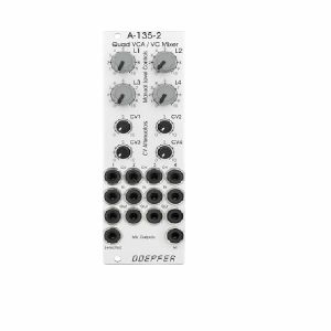
Doepfer A-135-2 Quad VCA & Voltage Controller Mixer Module (silver) (VCA/mixer synth module)
Cat: 714704 Rel: 22 Jan 19
Compact voltage-controlled four-channel audio mixer - 8HP
Notes: A-135-2 is a miniature version of the A-135-1. Behind a front panel with 8 HP only four linear VCAs (voltage controlled amplifiers) and a voltage controlled mixer based on the VCAs are available.
Controls, In/Outputs and Functions of each VCA:
- Level (manual control of the VCA amplification), small rubberized knob (L1...L4)
- Control voltage input with associated attenuator (CV1...CV4), for the full VCA control range about 0...+5V control voltage are required (attenuator fully clockwise), for higher control voltages the attenuator is used, the attenuators are without knobs, just plastic shafts with white marker
- Signal Input
- Signal Output
- All inputs and outputs are DC coupled. Consequently the VCAs can be used to process both audio and control voltages (e.g. to control the level of LFOs or envelopes)
- The signal input is not equipped with an attenuator. But the VCAs can process all signals up to 15Vpp / -7.5...+7.5V without clipping. In case of higher levels an external attenuator is required (e.g. A-183-1).
- The available amplification range is 0...1, the maximal amplification is 1 (i.e. it "clips" and remains at 1 even if the control voltage goes beyond the value that corresponds to amplification 1)
Functions of the voltage controlled mixers:
- Two outputs ("Selected" and "All")
- Selected output: the ouput if a VCA is removed from this sum signal when a plug is inserted into the corresponding VCA output.
- All output: sum of all VCA outputs, regardless of inserted plugs into the VCA outputs
- The maximal amplification is about 0.6 to avoid clipping at the mixer outputs (otherwise the outputs may distort with 15Vpp signals at each signal input and full amplifications)
Special functions of the voltage controlled mixers (selectable by internal jumpers):
- Dual Stereo VCA: In this case the control unit of VCA1 (L1 + CV1) affects also VCA3 and the control unit of VCA2 (L2 + CV2) affects also VCA4, the control units of VCA2 and VCA4 are out of operation
- Quad VCA: In this case the control unit of VCA1 (L1 + CV1) affects all four VCAs. The control units of VCA2, VCA3 and VCA4 are out of operation. In this mode the module has the same function as module A-132-2. That's why module A-132-2 will be discontinued.
- Normalling of the signal inputs: by means of internal jumpers signal input 1 can be normalled to signal input 2, signal input 2 to signal input 3 and signal input 3 to signal input In 4. That way the same input signal can be distributed to four different channels by means of control voltages (e.g. quadrophonic distribution of audio signals). Suitable control voltage sources are e.g. A-144 (Morphing Controller) or A-143-9 (Quadrature LFO).
… Read moreControls, In/Outputs and Functions of each VCA:
- Level (manual control of the VCA amplification), small rubberized knob (L1...L4)
- Control voltage input with associated attenuator (CV1...CV4), for the full VCA control range about 0...+5V control voltage are required (attenuator fully clockwise), for higher control voltages the attenuator is used, the attenuators are without knobs, just plastic shafts with white marker
- Signal Input
- Signal Output
- All inputs and outputs are DC coupled. Consequently the VCAs can be used to process both audio and control voltages (e.g. to control the level of LFOs or envelopes)
- The signal input is not equipped with an attenuator. But the VCAs can process all signals up to 15Vpp / -7.5...+7.5V without clipping. In case of higher levels an external attenuator is required (e.g. A-183-1).
- The available amplification range is 0...1, the maximal amplification is 1 (i.e. it "clips" and remains at 1 even if the control voltage goes beyond the value that corresponds to amplification 1)
Functions of the voltage controlled mixers:
- Two outputs ("Selected" and "All")
- Selected output: the ouput if a VCA is removed from this sum signal when a plug is inserted into the corresponding VCA output.
- All output: sum of all VCA outputs, regardless of inserted plugs into the VCA outputs
- The maximal amplification is about 0.6 to avoid clipping at the mixer outputs (otherwise the outputs may distort with 15Vpp signals at each signal input and full amplifications)
Special functions of the voltage controlled mixers (selectable by internal jumpers):
- Dual Stereo VCA: In this case the control unit of VCA1 (L1 + CV1) affects also VCA3 and the control unit of VCA2 (L2 + CV2) affects also VCA4, the control units of VCA2 and VCA4 are out of operation
- Quad VCA: In this case the control unit of VCA1 (L1 + CV1) affects all four VCAs. The control units of VCA2, VCA3 and VCA4 are out of operation. In this mode the module has the same function as module A-132-2. That's why module A-132-2 will be discontinued.
- Normalling of the signal inputs: by means of internal jumpers signal input 1 can be normalled to signal input 2, signal input 2 to signal input 3 and signal input 3 to signal input In 4. That way the same input signal can be distributed to four different channels by means of control voltages (e.g. quadrophonic distribution of audio signals). Suitable control voltage sources are e.g. A-144 (Morphing Controller) or A-143-9 (Quadrature LFO).
1 in stock $131.52
こんな商品も購入されています...
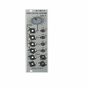
Doepfer A-185-2 Precision Adder/Bus Access Module (silver) (multiple/attenuator/mixer/utility/controller/switch synth module)
Cat: 751763 Rel: 23 Oct 19
Precision adder (mixer) and buffer for control voltages - 6HP
Notes: Module A-185-2 is a precision control voltage adder/buffer. Precision means that the amplification of the inputs without attenuators is exactly 1.00 and is suitable to add control voltages for the pitch control of VCOs (e.g. from keyboard + sequencer 1 + sequencer 2). Summing resistors matched to 0.1% are used to obtain an accuracy of 0.1% for the added voltages.
The module is equipped with four CV inputs: one with attenuator and three without attenuator. Each input is normalled to +1 V (i.e. if no plug is inserted the input contributes 1 V to the sum appearing at the output).
The input with attenuator can be used for common modulations (e.g. from an LFO, ADSR, Theremin, Pitch-Bender) for all VCOs connected to the output. The Lev.1 control is used to adjust the depth of the modulation, the first switch selects the polarity of the modulation. If no signal is connected to the first socket the attenuator works as a (fine) tuning knob because a voltage in the range 0...+1V (right position of the switch) or 0...-1V (left position of the switch) is added to the CV output.
The inputs without attenuators are planned to add control voltages coming out of keyboards, sequencers, Midi-to-CV interfaces, ribbon controllers or other CV sources that follow the 1V/oct standard. For example the CV of a keyboard can be used to transpose the CV coming from a sequencer, or the CV of a slow sequencer can be used to transpose the CV from a fast sequencer.
Each input is equipped with a three-position switch that determines if the corresponding voltage is added (right position), subtracted (left position) or if the input has no effect (centre position). If no plug is inserted the corresponding switch works as an octave switch for the lower three sections as the default 1 V are added or subtracted to the output voltage according to the switch position. The first switch can be used to add a variable voltage to the sum output. The variable voltage is adjusted with the Lev.1 control and the knob works then as kind of a (fine) tuning control.
The module is equipped with 4 outputs: three non-inverting and one inverting ouput. An internal jumper can be used to connect the non-inverted or inverted output to the CV line of the A-100 bus. That way the module can used to control several VCOs that are connected to the same bus board as the A-185-2 (same functionality as A-185-1).
… Read moreThe module is equipped with four CV inputs: one with attenuator and three without attenuator. Each input is normalled to +1 V (i.e. if no plug is inserted the input contributes 1 V to the sum appearing at the output).
The input with attenuator can be used for common modulations (e.g. from an LFO, ADSR, Theremin, Pitch-Bender) for all VCOs connected to the output. The Lev.1 control is used to adjust the depth of the modulation, the first switch selects the polarity of the modulation. If no signal is connected to the first socket the attenuator works as a (fine) tuning knob because a voltage in the range 0...+1V (right position of the switch) or 0...-1V (left position of the switch) is added to the CV output.
The inputs without attenuators are planned to add control voltages coming out of keyboards, sequencers, Midi-to-CV interfaces, ribbon controllers or other CV sources that follow the 1V/oct standard. For example the CV of a keyboard can be used to transpose the CV coming from a sequencer, or the CV of a slow sequencer can be used to transpose the CV from a fast sequencer.
Each input is equipped with a three-position switch that determines if the corresponding voltage is added (right position), subtracted (left position) or if the input has no effect (centre position). If no plug is inserted the corresponding switch works as an octave switch for the lower three sections as the default 1 V are added or subtracted to the output voltage according to the switch position. The first switch can be used to add a variable voltage to the sum output. The variable voltage is adjusted with the Lev.1 control and the knob works then as kind of a (fine) tuning control.
The module is equipped with 4 outputs: three non-inverting and one inverting ouput. An internal jumper can be used to connect the non-inverted or inverted output to the CV line of the A-100 bus. That way the module can used to control several VCOs that are connected to the same bus board as the A-185-2 (same functionality as A-185-1).
2 in stock $77.27
こんな商品も購入されています...
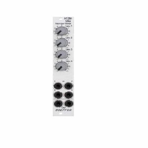
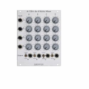
Doepfer A-138m 4x4 Matrix Mixer Module (mixer synth module)
Cat: 716959 Rel: 29 Jan 19
4x4 matrix mixer module - 20HP
Notes: Module A-138m is a 4 x 4 matrix mixer with switches for unipolar/bipolar mode for each column. Unipolar means that the controls work as attenuators. Bipolar means that the controls work as polarizers. In this mode the amplification is zero in the middle position of the corresponding control. Turning the knob counterclockwise from the center position the signal is subtracted from the output sum with increasing amount (i.e. negative). Turning the knob clockwise from the center position the signal is added to the output sum with increasing amount. The module is DC-coupled and can be used for both audio and control voltage mixing.
By means of an internal jumper one can select if the four upper controls work as DC offset generators - provided that no patch cord is plugged into the upper input socket. If this feature is not required it can be deactivated by removing the jumper on top left of the pc board. The function is identical to the A-138a/b.
Dimensions
20 HP
20 mm deep
Current Draw
30 mA +12V
30 mA -12V
… Read moreBy means of an internal jumper one can select if the four upper controls work as DC offset generators - provided that no patch cord is plugged into the upper input socket. If this feature is not required it can be deactivated by removing the jumper on top left of the pc board. The function is identical to the A-138a/b.
Dimensions
20 HP
20 mm deep
Current Draw
30 mA +12V
30 mA -12V
1 in stock $153.09
こんな商品も購入されています...
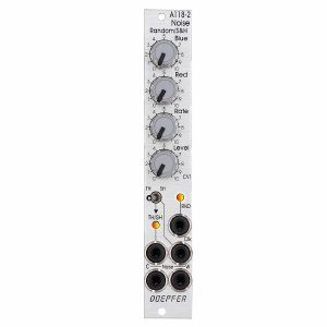
Doepfer A-118-2 Noise/Random/Sample & Hold Module (silver, slim line series) (noise/random/sample & hold synth module)
Cat: 731938 Rel: 10 Jun 19
Noise, random, sample & hold module - 4HP
Notes: Module A-118-2 is the slim version of module A-118-1 and offers essentially the same features as the A-118-1. But the distances between the controls are smaller and rubberized small-sized knobs are used. In return the front panel has 4 HP only which is half the width of the A-118-1. The module is primarily planned for applications where only limited space is available. The functional difference between A-118-1 and A-118-2 is the additional T&H/S&H unit which is not included in the A-118-1.
The module generates the signals white noise, colored noise, continuous random voltage and stepped random voltage (derived from the continuous random voltage by means of a S&H/T&H unit).
The noise signal is generated 100% analog by amplification of the noise of a transistor. White and colored noise are usually used as audio sources. The random voltages are normally used as control voltages (e.g. for filter frequency or any other voltage controlled parameter).
The A-118-2 gives you the ability to mix the relative amounts of Red (low frequency component) and Blue noise (high frequency component) in the colored noise output.
For the continuous random voltage the rate of change (Rate) and amplitude (Level) of the random voltage can be adjusted. The continuous random voltage is derived from the colored noise signal by low pass filtering. Consequently the settings of the controls for the colored noise (Blue, Red) affect the behavior of the random voltage! A dual color LED (red = positive / yellow = negative output voltage) indicates the continuous random voltage.
The continuous random voltage is used as source for the S&H/T&H unit. The type of operation can be set to S&H (sample and hold) or T&H (track and hold). When T&H is chosen the output signal follows the input signal (= continuous random voltage) as long as the Clock input is "high". As soon as the clock signal changes to "low" the last voltage is stored. When S&H is chosen the input signal (= continuous random voltage) is sampled at the rising edge of the Clock signal.
For the Clock signal a "digital" signal (e.g. Clock, Gate, rectangle output of an LFO) is required. It does not work with slowly changing continuous CV signals. Another dual color LED (red = positive / yellow = negative output voltage) indicates the stepped random voltage.
Controls:
Blue: share of the high frequencies in the the colored noise output
Red: share of the low frequencies in the the colored noise output
Rate: rate of change of the continuous random voltage
Level: amplitude of the continuous random voltage
TH/SH: switches between T&H and S&H
Inputs and outputs:
RND: continuous random voltage output (with LED display)
TH/SH: stepped random voltage output (with LED display)
Clk: Clock input of the S&H/T&H unit
C Noise: colored noise output
W Noise: white noise output
Important notes:
After power on it takes a few minutes until the two noise signals and the random signals are generated. The module is not faulty when after power on the signals do not appear immediately!
The S&H/T&H function is realized by pure analog circuitry (electronic switch followed by a holding capacitor and buffer). Consequently the output voltage drifts a bit in the holding state because the capacitor is discharged by parasitic resistors. The drift depends also upon environmental conditions like humidity or temperature.
Dimensions
4 HP
40 mm deep
Current Draw
20 mA +12V
20 mA -12V
… Read moreThe module generates the signals white noise, colored noise, continuous random voltage and stepped random voltage (derived from the continuous random voltage by means of a S&H/T&H unit).
The noise signal is generated 100% analog by amplification of the noise of a transistor. White and colored noise are usually used as audio sources. The random voltages are normally used as control voltages (e.g. for filter frequency or any other voltage controlled parameter).
The A-118-2 gives you the ability to mix the relative amounts of Red (low frequency component) and Blue noise (high frequency component) in the colored noise output.
For the continuous random voltage the rate of change (Rate) and amplitude (Level) of the random voltage can be adjusted. The continuous random voltage is derived from the colored noise signal by low pass filtering. Consequently the settings of the controls for the colored noise (Blue, Red) affect the behavior of the random voltage! A dual color LED (red = positive / yellow = negative output voltage) indicates the continuous random voltage.
The continuous random voltage is used as source for the S&H/T&H unit. The type of operation can be set to S&H (sample and hold) or T&H (track and hold). When T&H is chosen the output signal follows the input signal (= continuous random voltage) as long as the Clock input is "high". As soon as the clock signal changes to "low" the last voltage is stored. When S&H is chosen the input signal (= continuous random voltage) is sampled at the rising edge of the Clock signal.
For the Clock signal a "digital" signal (e.g. Clock, Gate, rectangle output of an LFO) is required. It does not work with slowly changing continuous CV signals. Another dual color LED (red = positive / yellow = negative output voltage) indicates the stepped random voltage.
Controls:
Blue: share of the high frequencies in the the colored noise output
Red: share of the low frequencies in the the colored noise output
Rate: rate of change of the continuous random voltage
Level: amplitude of the continuous random voltage
TH/SH: switches between T&H and S&H
Inputs and outputs:
RND: continuous random voltage output (with LED display)
TH/SH: stepped random voltage output (with LED display)
Clk: Clock input of the S&H/T&H unit
C Noise: colored noise output
W Noise: white noise output
Important notes:
After power on it takes a few minutes until the two noise signals and the random signals are generated. The module is not faulty when after power on the signals do not appear immediately!
The S&H/T&H function is realized by pure analog circuitry (electronic switch followed by a holding capacitor and buffer). Consequently the output voltage drifts a bit in the holding state because the capacitor is discharged by parasitic resistors. The drift depends also upon environmental conditions like humidity or temperature.
Dimensions
4 HP
40 mm deep
Current Draw
20 mA +12V
20 mA -12V
1 in stock $92.07
Click for better price!
or call +44 20 7424 1960
quote 731938
quote 731938
こんな商品も購入されています...
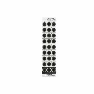
Doepfer A-130-8 Octal Linear VCA Module (slim line series, silver) (VCA synth module)
Cat: 765896 Rel: 28 Jul 20
Octal linear voltage controlled amplifier module - 6HP
Notes: Module A-130-8 contains eight linear voltage controlled amplifiers (VCAs). Each VCA features a control voltage input (CV), a signal input (In) and a signal output (Out). In addition three mixers are included: the socket labelled "1-4" outputs the sum of the VCAs 1-4, the socket labelled "5-8" outputs the sum of the VCAs 5-8, the socket labelled "1-8" outputs the sum of all eight VCAs.
The signal inputs are able to process levels up to about 20Vpp without clipping (20Vpp = 20V peak-to-peak or about -10V...+10V) . Each CV input is equipped with a trimming potentiometer that is used to adjust the sensitivity of the CV input in question. In the factory the module is adjusted for the CV range 0...+5V but can be re-adjusted by the user for other control voltage ranges (e.g. 0...+10V).
The amplification range for each single VCA is 0...1. The signals of the sum outputs have a lower amplification to avoid distortion at the sum outputs.
The VCAs and mixers are fully DC coupled, i.e. the module can be used for the processing of both audio and control voltage signals. The control voltage and signal inputs can be normalled by means of small solder pads (e.g. 1 > 2 > 3 > 4 and so on, or 1 > 5, 2 > 6, 3 > 7, 4 > 8 for the stereo application mentioned below).
Typical applications
any kind of VCA application (e.g. voltage controlled attenuation of audio or control voltage signals)
two voltage controlled mixers with four channels each
voltage controlled stereo mixer with four channels each, for this the control voltage inputs have to be correspondingly patched or internally normalled: CV1=CV5 /CV 2=CV6 / CV3=CV7 / CV4=CV8
voltage controlled mixer with eight channels
add-on for the Joystick module A-174-4
Technical notes
The following document shows the positions and functions of the jumpers and trimming potentiometers of the module: A130_8_trimming_potentiometers_and_jumpers.pdf
When the trimming potentiometer in question is moved CCW (counterclockwise) the sensitivity of the CV input in question increases (view to the top edge of the module).
Trimming procedure: apply the max. CV voltage that will occur in your application (e.g. +8V) to the CV input and a constant audio signal to the audio input (e.g. a VCO sawtooth). Then adjust the trimming potentiometer in question until the max. output level is reached and does not become higher even if the trimming potentiometer is turned further. Possible the the trimming potentiometer has to be turned back again a bit to find the correct position.
With the trimming potentiometer adjusted to max. sensitivity the linear amplification starts at about +0.1 control voltage (CV). We introduced this small dead range of about 100 mV to make sure that the VCA fully closes with CV = 0V.
It's possible to change the amplifications of the internal mixers used for the sum outputs (1-4, 1-8, 5-8) also to 1. Pay attention that then clipping/distortion may occur at the sum outputs. For this the 22k resistors R41 (Sum 1-4), R44 (Sum 5-8) und R51 (Sum 1-8) have to be replaced by 47k. As they are smd resistors sufficient experience with soldering/desoldering of smd parts is essential. And we have to point out that warranty is void if such modifications are carried out by the customer. The positions of the resistors are shown in the document A130_8_trimming_potentiometers_and_jumpers.pdf.
If multiple exponential VCAs are required module A-132-4 is recommended.
Width: 6 HP / 30.1 mm
Depth: 40 mm (measured from the rear side of the front panel)
Current: +50 mA (+12V) / -50 mA (-12V)
… Read moreThe signal inputs are able to process levels up to about 20Vpp without clipping (20Vpp = 20V peak-to-peak or about -10V...+10V) . Each CV input is equipped with a trimming potentiometer that is used to adjust the sensitivity of the CV input in question. In the factory the module is adjusted for the CV range 0...+5V but can be re-adjusted by the user for other control voltage ranges (e.g. 0...+10V).
The amplification range for each single VCA is 0...1. The signals of the sum outputs have a lower amplification to avoid distortion at the sum outputs.
The VCAs and mixers are fully DC coupled, i.e. the module can be used for the processing of both audio and control voltage signals. The control voltage and signal inputs can be normalled by means of small solder pads (e.g. 1 > 2 > 3 > 4 and so on, or 1 > 5, 2 > 6, 3 > 7, 4 > 8 for the stereo application mentioned below).
Typical applications
any kind of VCA application (e.g. voltage controlled attenuation of audio or control voltage signals)
two voltage controlled mixers with four channels each
voltage controlled stereo mixer with four channels each, for this the control voltage inputs have to be correspondingly patched or internally normalled: CV1=CV5 /CV 2=CV6 / CV3=CV7 / CV4=CV8
voltage controlled mixer with eight channels
add-on for the Joystick module A-174-4
Technical notes
The following document shows the positions and functions of the jumpers and trimming potentiometers of the module: A130_8_trimming_potentiometers_and_jumpers.pdf
When the trimming potentiometer in question is moved CCW (counterclockwise) the sensitivity of the CV input in question increases (view to the top edge of the module).
Trimming procedure: apply the max. CV voltage that will occur in your application (e.g. +8V) to the CV input and a constant audio signal to the audio input (e.g. a VCO sawtooth). Then adjust the trimming potentiometer in question until the max. output level is reached and does not become higher even if the trimming potentiometer is turned further. Possible the the trimming potentiometer has to be turned back again a bit to find the correct position.
With the trimming potentiometer adjusted to max. sensitivity the linear amplification starts at about +0.1 control voltage (CV). We introduced this small dead range of about 100 mV to make sure that the VCA fully closes with CV = 0V.
It's possible to change the amplifications of the internal mixers used for the sum outputs (1-4, 1-8, 5-8) also to 1. Pay attention that then clipping/distortion may occur at the sum outputs. For this the 22k resistors R41 (Sum 1-4), R44 (Sum 5-8) und R51 (Sum 1-8) have to be replaced by 47k. As they are smd resistors sufficient experience with soldering/desoldering of smd parts is essential. And we have to point out that warranty is void if such modifications are carried out by the customer. The positions of the resistors are shown in the document A130_8_trimming_potentiometers_and_jumpers.pdf.
If multiple exponential VCAs are required module A-132-4 is recommended.
Width: 6 HP / 30.1 mm
Depth: 40 mm (measured from the rear side of the front panel)
Current: +50 mA (+12V) / -50 mA (-12V)
1 in stock $114.03
こんな商品も購入されています...
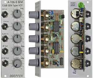
Doepfer A-106-5 SEM 12dB SEM Type VCF Module (silver) (filter synth module)
Cat: 577753 Rel: 06 Jun 19
12dB multi-mode filter - 8HP
Notes: Module A-106-5 is a 12dB multimode filter that is based on the filter circuit of the Oberheim SEM module.
The filter is equipped with a band pass output and a combined low/notch/high pass output. For this output a control knob defines the relation between low and high pass signal. If both signals appear at the same level (i.e. middle position of the Mix knob) one obtains a notch filter. Otherwise the low or high pass signal predominates.
The module does not feature self-oscillation in contrast to most of the other filters of the A-100 system.
The module generates a distorted audio signal if the level control is set to about 50% (i.e. centre position) or more with A-100 standard signals like VCOs.
… Read moreThe filter is equipped with a band pass output and a combined low/notch/high pass output. For this output a control knob defines the relation between low and high pass signal. If both signals appear at the same level (i.e. middle position of the Mix knob) one obtains a notch filter. Otherwise the low or high pass signal predominates.
The module does not feature self-oscillation in contrast to most of the other filters of the A-100 system.
The module generates a distorted audio signal if the level control is set to about 50% (i.e. centre position) or more with A-100 standard signals like VCOs.
1 in stock $92.07
Click for better price!
or call +44 20 7424 1960
quote 577753
quote 577753
こんな商品も購入されています...
Doepfer A-182-2 Quad Passive Switch Module (silver, slim line series) (switch synth module)
Cat: 731951 Rel: 11 Jun 19
Quad passive switch - 4HP
Notes: A-182-2 is a simple passive module that contains four changeover switches, which are used to connect or disconnect the sockets of the corresponding socket triplet:
- In the upper position of the switch the upper socket of the corresponding socket triplet is connected to the centre socket
- In the lower position of the switch the lower socket of the corresponding socket triplet is connected to the centre socket
- In the centre position of the switch the sockets are not connected
Each unit of the module can be used to switch between two signals or to interrupt/connect a signal. In the last case the third socket of the triplet is not used.
The module is fully passive and both audio or control signals can be switched.
… Read more- In the upper position of the switch the upper socket of the corresponding socket triplet is connected to the centre socket
- In the lower position of the switch the lower socket of the corresponding socket triplet is connected to the centre socket
- In the centre position of the switch the sockets are not connected
Each unit of the module can be used to switch between two signals or to interrupt/connect a signal. In the last case the third socket of the triplet is not used.
The module is fully passive and both audio or control signals can be switched.
1 in stock $65.45
Click for better price!
or call +44 20 7424 1960
quote 731951
quote 731951
こんな商品も購入されています...
Doepfer A-180-2 Passive Multiple Module (silver) (dual/stereo/multiple/utility module)
Cat: 577779 Rel: 14 Jun 19
Passive multi-port distributor - 2HP
Notes: 2HP narrow version of the A-180 multiples module. It is a passive signal splitter suitable for audio or CVs. Two sets of four jacks are interconnected, by placing a solder bridge you can connect all eight jacks.
Dimensions
2 HP
18 mm deep
Current Draw
Module does not draw current
… Read moreDimensions
2 HP
18 mm deep
Current Draw
Module does not draw current
6 in stock $36.89
こんな商品も購入されています...
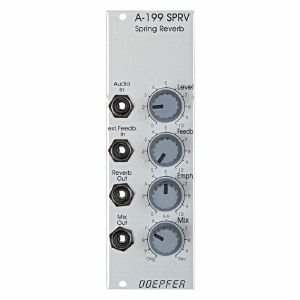
Doepfer A-199 SPRV Federhall Spring Reverb Module (silver) (effect/reverb synth module)
Cat: 577748 Rel: 15 Aug 18
Reverb effects module with spring reverb tank - 8HP
Notes: Module A-199 is a spring reverb module. The reverb effect is electronically simulated by means of 3 spiral springs. Spring reverb systems have a very characteristic sound that is based on the (insufficient) mechanical properties of the springs like signal delays, audio resonances, limited frequency range, acoustic feedback behaviour, sensitivity to mechanical shocks and others.
The 3-spring system used in the A-199 ensures a "dense" reverb because of the different properties of the three springs.
The A-199 implies some special features that are not self-evident for spring reverb units:
The reverb signal can be fed back to the input using the Feedback control. Even self-oscillation of the springs similar to the self-oscillation of filters is available. The feedback loop can lead even via external modules like VCA, VCF, phaser, frequency shifter, vocoder, distortion/waveshaper, ring modulator and others. In this case the reverb output of the A-199 is connected to the input of the external module(s) and the output of the external module(s) is fed back to the Ext. Feedback In socket of the A-199. This socket contains a switch that interrupts the internal feedback loop as soon as a plug is inserted.
Another feature is the Emphasis control. This enables the adjustment of the accentuation of middle frequencies (around ~ 2kHz).
With the Mix control the relation between original and reverb signal appearing at the mix output is adjusted.
Using all these features very extreme and unusual effects can be generated with the A-199.
… Read moreThe 3-spring system used in the A-199 ensures a "dense" reverb because of the different properties of the three springs.
The A-199 implies some special features that are not self-evident for spring reverb units:
The reverb signal can be fed back to the input using the Feedback control. Even self-oscillation of the springs similar to the self-oscillation of filters is available. The feedback loop can lead even via external modules like VCA, VCF, phaser, frequency shifter, vocoder, distortion/waveshaper, ring modulator and others. In this case the reverb output of the A-199 is connected to the input of the external module(s) and the output of the external module(s) is fed back to the Ext. Feedback In socket of the A-199. This socket contains a switch that interrupts the internal feedback loop as soon as a plug is inserted.
Another feature is the Emphasis control. This enables the adjustment of the accentuation of middle frequencies (around ~ 2kHz).
With the Mix control the relation between original and reverb signal appearing at the mix output is adjusted.
Using all these features very extreme and unusual effects can be generated with the A-199.
1 in stock $118.70
こんな商品も購入されています...
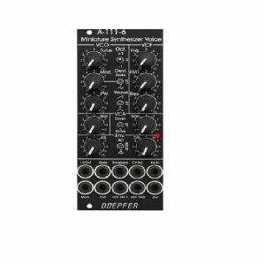
Doepfer A-111-6v Miniature Synthesiser Voice Vintage Edition Module (black) (synth voice synth module)
Cat: 749811 Rel: 15 Nov 19
Complete miniature monophonic synthesiser module - 10HP
Notes: VCO:
- Tune: manual tune control (with an internal jumper the range can be set to ~ +/-1 half an octave or ~ +/-2.5 octaves)
- Oct: range switch -1 / 0 / +1 octave
- Mod: modulation depth (attenuator wired to the Mod. socket)
- Dest: switch that is used to address the modulation to frequency modulation (position FM) or pulsewidth modulation (positon PM), in centre positon no modulation
- PW: manual pulsewidth control for rectangle waveform, PW can be also modulated by the Mod. input as mentioned above
- Wave: waveform switch (sawtooth / off / triangle), the sum of the waveform chosen by this switch and the rectangle is fed into the VCF (to turn the rectangle off the PW control has to be set fully CCW or fully CW)
- 1V/Oct. (socket): external CV input for VCO frequency (1V/octave)
- Access to internal bus CV (via jumper, optional, please remove the bus jumper if this feature is not used to avoid unwanted frequency modulation as then the unused CV line of the bus works as a kind of antenna)
- Triangle core VCO, frequency range about 32Hz ... 8kHz
Balance unit:
- The balance unit is made of two VCAs which are controlled by the sum of manual Balance control and the balance CV input in the opposite direction.
- The audio input of VCA1 is hard-wired to the VCO output, audio input 2 is connected to the socket Ext.In.
- The output of the balance unit is used as audio input for the VCF
- Bal.: manual balance control, fully CCW the internal VCO is used, fully CW the external signal (Ext.In) is used, at centre position both signals have about the same level
- CV Bal.: CV input for balance (range about 0...+5V)
- Ext. In: external audio input for VCA2, about 5 Vpp level required for similar loudness as the internal VCO
- This socket is normalled to the internal VCO suboctave f/2 signal (rectangle with half the frequency), if no external signal is applied the suboctave signal is used as the second signal for the balance unit
VCF:
- 24 dB low pass
- Frq: manual frequency control
- FM1: frequency modulation depth (attenuator wired to the VCF FM1 socket, the socket is normalled to the internal Envelope signal and then FM1 controls the modulation depth of the internal envelope applied to the filter)
- FM2 (socket) : second CV input for VCF without attenuator (about 1V/octave), can be used e.g. for VCF tracking by connecting the same CV which is used also for the VCO frequency
- Res: manual resonance control (up to self oscillation)
- If the VCO is turned off (waveform switch = centre position, pulsewidth control = fully CCW or CW) and the VCF resonance is set to maximum the module can be used as a sine oscillator, the tracking at socket VCF FM2 is about 1V/octave (not as precise as the VCO but much better than most other filters)
- ~ 11 octaves frequency range (~ 10 Hz ... 20kHz)
VCA:
- Gain: manual amplitude control (initial gain), can be used to open the VCA without envelope signal
- VCA (switch): used to switch between gate and envelope as control signal for the VCA, in centre position the VCA is not controlled by envelope or gate
- Note: when gate is used the VCA is controlled directly by the gate signal (i.e. hard on/off), this may lead to clicking noise under certain conditions (especially with low VCO/VCF frequencies)
- Special control scale: exponential scale in the range from about -20dB to -80/90dB, linear scale from about -20dB to 0dB
- Remark: this special control scale results in a loudness behaviour that is a bit different from pure linear or exponential VCAs
- Out: audio output of the module (= VCA output)
Envelope:
- Gate (socket): Gate input (min. +5V), can be normalled to the bus gate signal by means of a jumper
- Att: manual control for Attack
- D/R: manual control for Decay/Release
- Env. (switch): used to switch between A/D, ADSR and A/R mode of the envelope generator, in centre position (ADSR) the sustain level is fixed to about 50%
- Envelope (socket): envelope output (about +10V)
- CVT (socket): CV input for time control, by means of two internal jumpers one can select which time parameters are controlled by the CVT input (e.g. A only or D/R only or A/D/R) and in which direction (i.e. if an increasing CVT shortens or stretches the time parameter in question)
- Envelope LED display
- Attack time range: ~ 1ms ... 5 sec (can be extended by using the CVT input)
- Decay/Release time range: ~ 1ms ... 15 sec (can be extended by using the CVT input)
… Read more- Tune: manual tune control (with an internal jumper the range can be set to ~ +/-1 half an octave or ~ +/-2.5 octaves)
- Oct: range switch -1 / 0 / +1 octave
- Mod: modulation depth (attenuator wired to the Mod. socket)
- Dest: switch that is used to address the modulation to frequency modulation (position FM) or pulsewidth modulation (positon PM), in centre positon no modulation
- PW: manual pulsewidth control for rectangle waveform, PW can be also modulated by the Mod. input as mentioned above
- Wave: waveform switch (sawtooth / off / triangle), the sum of the waveform chosen by this switch and the rectangle is fed into the VCF (to turn the rectangle off the PW control has to be set fully CCW or fully CW)
- 1V/Oct. (socket): external CV input for VCO frequency (1V/octave)
- Access to internal bus CV (via jumper, optional, please remove the bus jumper if this feature is not used to avoid unwanted frequency modulation as then the unused CV line of the bus works as a kind of antenna)
- Triangle core VCO, frequency range about 32Hz ... 8kHz
Balance unit:
- The balance unit is made of two VCAs which are controlled by the sum of manual Balance control and the balance CV input in the opposite direction.
- The audio input of VCA1 is hard-wired to the VCO output, audio input 2 is connected to the socket Ext.In.
- The output of the balance unit is used as audio input for the VCF
- Bal.: manual balance control, fully CCW the internal VCO is used, fully CW the external signal (Ext.In) is used, at centre position both signals have about the same level
- CV Bal.: CV input for balance (range about 0...+5V)
- Ext. In: external audio input for VCA2, about 5 Vpp level required for similar loudness as the internal VCO
- This socket is normalled to the internal VCO suboctave f/2 signal (rectangle with half the frequency), if no external signal is applied the suboctave signal is used as the second signal for the balance unit
VCF:
- 24 dB low pass
- Frq: manual frequency control
- FM1: frequency modulation depth (attenuator wired to the VCF FM1 socket, the socket is normalled to the internal Envelope signal and then FM1 controls the modulation depth of the internal envelope applied to the filter)
- FM2 (socket) : second CV input for VCF without attenuator (about 1V/octave), can be used e.g. for VCF tracking by connecting the same CV which is used also for the VCO frequency
- Res: manual resonance control (up to self oscillation)
- If the VCO is turned off (waveform switch = centre position, pulsewidth control = fully CCW or CW) and the VCF resonance is set to maximum the module can be used as a sine oscillator, the tracking at socket VCF FM2 is about 1V/octave (not as precise as the VCO but much better than most other filters)
- ~ 11 octaves frequency range (~ 10 Hz ... 20kHz)
VCA:
- Gain: manual amplitude control (initial gain), can be used to open the VCA without envelope signal
- VCA (switch): used to switch between gate and envelope as control signal for the VCA, in centre position the VCA is not controlled by envelope or gate
- Note: when gate is used the VCA is controlled directly by the gate signal (i.e. hard on/off), this may lead to clicking noise under certain conditions (especially with low VCO/VCF frequencies)
- Special control scale: exponential scale in the range from about -20dB to -80/90dB, linear scale from about -20dB to 0dB
- Remark: this special control scale results in a loudness behaviour that is a bit different from pure linear or exponential VCAs
- Out: audio output of the module (= VCA output)
Envelope:
- Gate (socket): Gate input (min. +5V), can be normalled to the bus gate signal by means of a jumper
- Att: manual control for Attack
- D/R: manual control for Decay/Release
- Env. (switch): used to switch between A/D, ADSR and A/R mode of the envelope generator, in centre position (ADSR) the sustain level is fixed to about 50%
- Envelope (socket): envelope output (about +10V)
- CVT (socket): CV input for time control, by means of two internal jumpers one can select which time parameters are controlled by the CVT input (e.g. A only or D/R only or A/D/R) and in which direction (i.e. if an increasing CVT shortens or stretches the time parameter in question)
- Envelope LED display
- Attack time range: ~ 1ms ... 5 sec (can be extended by using the CVT input)
- Decay/Release time range: ~ 1ms ... 15 sec (can be extended by using the CVT input)
1 in stock $210.78
こんな商品も購入されています...
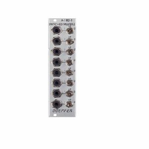
Doepfer A-182-1 Switched Multiples Module (switch/multiple synth module)
Cat: 751724 Rel: 23 Oct 19
Eurorack passive multi-connector - 6HP
Notes: Module A-182-1 is a simple passive multi-connector similar to the multiples modules A-180-1/A-180-2. In contrast to modules A-180-1/2 each socket is equipped with a 3-position switch that allows to connect the corresponding socket to the internal bus #1 (left position), bus #2 (right position) or to turn the socket off (centre position).
Examples:
- All switches in left position or all switches in right position: 8-fold multiple
- Four switches in left position and four switches in right position: two 4-fold multiple
- X switches in left position, Y switches in right position and Z switches in centre position: two separate multiples with some sockets turned off
… Read moreExamples:
- All switches in left position or all switches in right position: 8-fold multiple
- Four switches in left position and four switches in right position: two 4-fold multiple
- X switches in left position, Y switches in right position and Z switches in centre position: two separate multiples with some sockets turned off
1 in stock $61.57
こんな商品も購入されています...
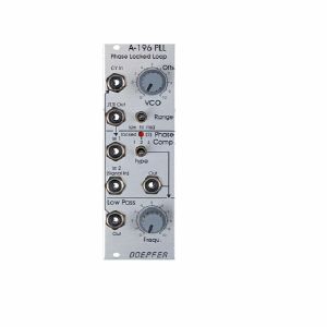
Doepfer A-196 PLL Phase Locked Loop Module (processing synth module)
Cat: 755416 Rel: 14 Nov 19
Eurorack phase locked loop module, featuring voltage-controlled oscillator, phase comparator & low pass filter
Notes: Module A-196 contains a so-called phase locked loop (PLL). The basic PLL system is shown in the sketch at the bottom of this page. A PLL consists of three parts: voltage-controlled oscillator (VCO), phase comparator (PC), and low-pass filter (LPF). All parts are normally connected to form a closed-loop frequency-feedback system.
This is how a PLL works: The output of the internal VCO (linear CV control, rectangle output) is compared with an external signal (e.g. the rectangle output of a A-110 VCO) in the so-called phase comparator (PC). The output of the phase comparator is a digital signal (low/high/tristate) that indicates if the frequency resp. phase difference of the two input signals is negative, zero or positive. The output of the phase comparator is processed by a low pass filter (LPF) to generate a smooth voltage that is used to control the frequency of the internal VCO. The 3 units VCO, PC and LPF form a feedback loop that works like this: The control voltage (output of the LPF) increases as long as the external frequency is higher than the frequency of the internal VCO und stops increasing when both frequencies become identical. The control voltage decreases as long as the external frequency is lower than the frequency of the internal VCO und stops decreasing when both frequencies become identical.
But there are some stumbling blocks: Different types of phase comparators with advantages and disadvantages can be made. Some phase comparators e.g. even lock at harmonics, i.e. if the two frequencies to be compared are integer multiples. But for some applications this can be used to create interesting effects. The A-196 contains 3 different types of phase comparators: PC1 is a simple exclusive OR, that even locks at harmonics. PC2 is a so-called RS flipflop and PC3 a more complex digital memory network. The user can select one of the three phase comparators with a 3-position switch. When PC2 is used a LED displays the "locked" state, i.e. when the frequency of the internal VCO is identical to the external frequency.
Special attention has to be directed to the frequency of the LPF. To obtain a smooth control voltage for the VCO the frequency of the LPF has to be much smaller than the lowest frequency of the internal or external audio signal. Otherwise the frequency of the internal VCO will jitter or wobble around the correct frequency. But for special effects this frequency jitter can be used intentionally. Example: frequencies in the range 50Hz...1kHz have to be processed with the PLL. Therefore the frequency of the LPF has to be about 10Hz or even less. Such a low frequency of the LPF causes a noticeable slew of the internal VCO. When the frequency of the external signal jumps e.g. between 500Hz and 1kHz it takes about 0.1 second until the internal VCO reaches the new frequency (like portamento). So one has to find a compromise between frequency jitter and portamento. But these remarks are valid only for the "ideal" working PLL. As the A-196 is used in a musical environment the "problems" and disadvantages with jitter and slew time lead to additional musical applications like portamento effects, wobbling frequencies or harmonic locking according to the type of frequency comparator and time constant of the PLL low pass filter. Instead of the internal manually controlled low pass filter the voltage controlled slew limiter A-171 can be used to obtain voltage control of this parameter. Normal audio filters (e.g. A-120, A-121) cannot be used for this job as the minimum frequency is to high (down to a few Hz or even less necessary) and the signal has to be DC coupled due to the low frequencies. Audio filters are normally AC coupled.
Another very important application of a PLL is frequency multiplication in combination with an external frequency divider. For this the output of the PLL-VCO is processed through an external frequency divider (e.g. A-163, A-160, A-161, A-115) before it is fed to In1 of the phase comparator. In this case the frequency of the PLL-VCO will be a multiple of the master frequency. E.g. if the A-163 is used and adjusted to dividing factor 5 the frequency of the PLL-VCO will be 5 times the frequency of the master VCO. Consequently, frequency division (A-163) leads to frequency multiplication with the PLL circuit. In combination with the PLL low pass frequency several effects can be realized (frequency multiplication with portamento or wobbling). The frequency multiplication can even be used to drive a graphic VCO. If your graphic VCO e.g. has 8 steps (e.g. A-155) and you use a frequency divider with factor 8 in the PLL feedback the output of the graphic VCO has the same frequency as the master VCO. Another application is the generation of pseudo-harmonics (not real harmonics as only rectangle waves are available) or clock generation for switched-capacitor filters.
… Read moreThis is how a PLL works: The output of the internal VCO (linear CV control, rectangle output) is compared with an external signal (e.g. the rectangle output of a A-110 VCO) in the so-called phase comparator (PC). The output of the phase comparator is a digital signal (low/high/tristate) that indicates if the frequency resp. phase difference of the two input signals is negative, zero or positive. The output of the phase comparator is processed by a low pass filter (LPF) to generate a smooth voltage that is used to control the frequency of the internal VCO. The 3 units VCO, PC and LPF form a feedback loop that works like this: The control voltage (output of the LPF) increases as long as the external frequency is higher than the frequency of the internal VCO und stops increasing when both frequencies become identical. The control voltage decreases as long as the external frequency is lower than the frequency of the internal VCO und stops decreasing when both frequencies become identical.
But there are some stumbling blocks: Different types of phase comparators with advantages and disadvantages can be made. Some phase comparators e.g. even lock at harmonics, i.e. if the two frequencies to be compared are integer multiples. But for some applications this can be used to create interesting effects. The A-196 contains 3 different types of phase comparators: PC1 is a simple exclusive OR, that even locks at harmonics. PC2 is a so-called RS flipflop and PC3 a more complex digital memory network. The user can select one of the three phase comparators with a 3-position switch. When PC2 is used a LED displays the "locked" state, i.e. when the frequency of the internal VCO is identical to the external frequency.
Special attention has to be directed to the frequency of the LPF. To obtain a smooth control voltage for the VCO the frequency of the LPF has to be much smaller than the lowest frequency of the internal or external audio signal. Otherwise the frequency of the internal VCO will jitter or wobble around the correct frequency. But for special effects this frequency jitter can be used intentionally. Example: frequencies in the range 50Hz...1kHz have to be processed with the PLL. Therefore the frequency of the LPF has to be about 10Hz or even less. Such a low frequency of the LPF causes a noticeable slew of the internal VCO. When the frequency of the external signal jumps e.g. between 500Hz and 1kHz it takes about 0.1 second until the internal VCO reaches the new frequency (like portamento). So one has to find a compromise between frequency jitter and portamento. But these remarks are valid only for the "ideal" working PLL. As the A-196 is used in a musical environment the "problems" and disadvantages with jitter and slew time lead to additional musical applications like portamento effects, wobbling frequencies or harmonic locking according to the type of frequency comparator and time constant of the PLL low pass filter. Instead of the internal manually controlled low pass filter the voltage controlled slew limiter A-171 can be used to obtain voltage control of this parameter. Normal audio filters (e.g. A-120, A-121) cannot be used for this job as the minimum frequency is to high (down to a few Hz or even less necessary) and the signal has to be DC coupled due to the low frequencies. Audio filters are normally AC coupled.
Another very important application of a PLL is frequency multiplication in combination with an external frequency divider. For this the output of the PLL-VCO is processed through an external frequency divider (e.g. A-163, A-160, A-161, A-115) before it is fed to In1 of the phase comparator. In this case the frequency of the PLL-VCO will be a multiple of the master frequency. E.g. if the A-163 is used and adjusted to dividing factor 5 the frequency of the PLL-VCO will be 5 times the frequency of the master VCO. Consequently, frequency division (A-163) leads to frequency multiplication with the PLL circuit. In combination with the PLL low pass frequency several effects can be realized (frequency multiplication with portamento or wobbling). The frequency multiplication can even be used to drive a graphic VCO. If your graphic VCO e.g. has 8 steps (e.g. A-155) and you use a frequency divider with factor 8 in the PLL feedback the output of the graphic VCO has the same frequency as the master VCO. Another application is the generation of pseudo-harmonics (not real harmonics as only rectangle waves are available) or clock generation for switched-capacitor filters.
1 in stock $85.42
Click for better price!
or call +44 20 7424 1960
quote 755416
quote 755416
こんな商品も購入されています...
Doepfer A-180-3 Dual Buffered Multiple Module (silver) (dual/stereo/multiple synth module)
Cat: 751720 Rel: 23 Oct 19
Dual buffered 1-in-3 multiple module - 4HP
Notes: Module A-180-3 is a dual buffered 1-in-3 multiple. The signal applied to the input socket appears as a buffered signal at the three output sockets. Each output has its own buffer, i.e. the three output sockets are not simply connected to each other. The lower output of the upper unit is normalled in the factory to the input of the lower unit. That way the module works as a single 1-in-6 buffered multiple provided that no signal is applied to the input of the lower unit. But it's also possible to pick-up the bus CV and normalize the input socket of the lower unit to the bus CV.
Application: copying/buffering of CV, gate and audio signals.
… Read moreApplication: copying/buffering of CV, gate and audio signals.
1 in stock $55.46
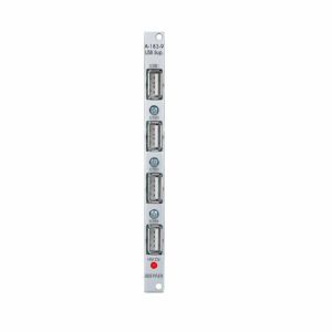
こんな商品も購入されています...
Doepfer A-183-9 Quad USB Power Supply Module (power synth module)
Cat: 711015 Rel: 29 Nov 18
Simple power supply for up to four devices - 2HP
Notes: Module A-183-9 is a simple power supply for up to four devices which can be powered via USB (e.g. keyboards, smartphones). An LED shows is the +5V are present.
The module has no USB function but provides only the +5V supply for USB devices.
A control LED shows if the +5V are present.
Note: The module requires an A-100 case with built in power supply A-100PSU3. Only this A-100 supply has the required +5V available. We do not recommend the usage of an older A-100 case with A-100PSU2 as this would require the +5V adapter A-100AD5 and the max. current would be limited to 100mA.
… Read moreThe module has no USB function but provides only the +5V supply for USB devices.
A control LED shows if the +5V are present.
Note: The module requires an A-100 case with built in power supply A-100PSU3. Only this A-100 supply has the required +5V available. We do not recommend the usage of an older A-100 case with A-100PSU2 as this would require the +5V adapter A-100AD5 and the max. current would be limited to 100mA.
! low stock $52.97
Click for better price!
or call +44 20 7424 1960
quote 711015
quote 711015
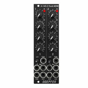
こんな商品も購入されています...
Doepfer A-140-2v Dual Mini ADSR Module (vintage edition) (envelope generator synth module)
Cat: 734880 Rel: 10 Jul 19
Envelope module with two ADSR voltage controlled enevelope generators - 8HP
Notes: The module contains two ADSR type voltage controlled envelope generators with exponential curve shapes (charge/discharge curves of a capacitor) behind a front panel with 8 HP only.
Each ADSR provides these controls and in/outputs:
- LED (displays the envelope output)
- A: manual Attack control
- D: manual Decay control
- S: manual Sustain control
- R: manual Release control
- Gate Input
- Retrigger Input
- CVT Input with attenuator (CVT = CV Time)
- Envelope Output 1
- Envelope Output 2
The output voltage range for each envelope is 0 - 10V (10V = attack peak).
The time range of Attack/Decay/Release is about 1ms to 30s.
By means of internal jumpers one can select which time parameters are controlled by the CVT input (e.g. D only or D+R or A+D+R) and in which direction (i.e. if an increasing CVT shortens or stretches the time parameter in question).
Socket CVT can be normalled to an internal fixed voltage (i.e. the switching contact is connected to an internal fixed voltage). That way it's possible to change all time parameters simultaneously by means of the CVT control.
Another jumper is used to set output 2 to normal or inverted envelope.
And another jumper is used for the normalling of Gate 2 to Gate 1 (i.e. ADSR#2 is also triggered by Gate 1).
Two more jumpers are used for the optional bus access to the gate signal of the bus for each ADSR.
… Read moreEach ADSR provides these controls and in/outputs:
- LED (displays the envelope output)
- A: manual Attack control
- D: manual Decay control
- S: manual Sustain control
- R: manual Release control
- Gate Input
- Retrigger Input
- CVT Input with attenuator (CVT = CV Time)
- Envelope Output 1
- Envelope Output 2
The output voltage range for each envelope is 0 - 10V (10V = attack peak).
The time range of Attack/Decay/Release is about 1ms to 30s.
By means of internal jumpers one can select which time parameters are controlled by the CVT input (e.g. D only or D+R or A+D+R) and in which direction (i.e. if an increasing CVT shortens or stretches the time parameter in question).
Socket CVT can be normalled to an internal fixed voltage (i.e. the switching contact is connected to an internal fixed voltage). That way it's possible to change all time parameters simultaneously by means of the CVT control.
Another jumper is used to set output 2 to normal or inverted envelope.
And another jumper is used for the normalling of Gate 2 to Gate 1 (i.e. ADSR#2 is also triggered by Gate 1).
Two more jumpers are used for the optional bus access to the gate signal of the bus for each ADSR.
1 in stock $161.97
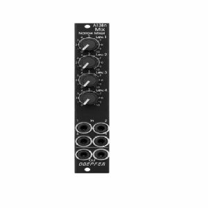
こんな商品も購入されています...
Doepfer A-138nv Narrow Mini Mixer Vintage Edition Module (black) (mixer/quad synth module)
Cat: 760211 Rel: 06 Mar 20
Narrow mini mixer module - 4HP.
Notes: Compact and simple four-input mixer module from Uncle Dieter. Linear pots make it suited to mixing CV signals but it can also handle audio. Mixed signal hard-wired to two sockets.
Supplier notes:
Module A-138n is a simple four channel mixer, which can be used with either control voltages or audio signals. Each of the four inputs has an attenuator available. The output is twice available (two sockets, hard-wired like a multiple).
HP : 4
… Read moreSupplier notes:
Module A-138n is a simple four channel mixer, which can be used with either control voltages or audio signals. Each of the four inputs has an attenuator available. The output is twice available (two sockets, hard-wired like a multiple).
HP : 4
1 in stock $75.43
Click for better price!
or call +44 20 7424 1960
quote 760211
quote 760211
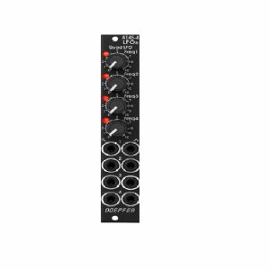
こんな商品も購入されています...
Doepfer A-145-4v Quad LFO Module (vintage edition) (LFO synth module)
Cat: 760210 Rel: 01 Apr 20
Quad low frequency oscillator module
Notes: Module A-145-4 is a simple quad LFO (Low Frequency Oscillator). Not a very "exciting" module, just a bread-and-butter device and a simple demon for work. Virtually in every modular system several LFOs are required for modulation purposes. The module contains four simple LFOs with the waveforms triangle and rectangle. A dual colour LED (red = positive / yellow = negative output voltage) indicates the triangle output of each LFO. The frequency range can be chosen for each LFO individually by means of a jumper between about 50 Hz ... 0.04 Hz (about 20 seconds, jumper removed) and about 2Hz ... 0.002 (about 8 minutes, jumper installed).
The module can be treated as a slimmed version of the quad LFO A-143-3 as it has similar features available. But the distances between the controls are smaller and rubberized small-sized knobs are used. In return the front panel has 4 HP only which is less than one third of the A-143-3. The module is primarily planned for applications where only limited space is available. The functional difference compared to the A-143-3 are the missing sawtooth outputs and frequency range switches.
… Read moreThe module can be treated as a slimmed version of the quad LFO A-143-3 as it has similar features available. But the distances between the controls are smaller and rubberized small-sized knobs are used. In return the front panel has 4 HP only which is less than one third of the A-143-3. The module is primarily planned for applications where only limited space is available. The functional difference compared to the A-143-3 are the missing sawtooth outputs and frequency range switches.
1 in stock $95.40
Click for better price!
or call +44 20 7424 1960
quote 760210
quote 760210
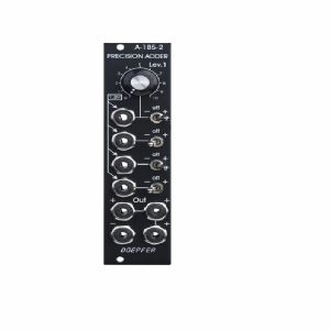
こんな商品も購入されています...
Doepfer A-185-2v Precision Adder/Bus Access Vintage Edition Module (black) (attenuator/CV modulation/mixer/multiple/utility synth module)
Cat: 751764 Rel: 23 Oct 19
Precision adder (mixer) and buffer for control voltages - 6HP
Notes: Module A-185-2 is a precision control voltage adder/buffer. Precision means that the amplification of the inputs without attenuators is exactly 1.00 and is suitable to add control voltages for the pitch control of VCOs (e.g. from keyboard + sequencer 1 + sequencer 2). Summing resistors matched to 0.1% are used to obtain an accuracy of 0.1% for the added voltages.
The module is equipped with four CV inputs: one with attenuator and three without attenuator. Each input is normalled to +1 V (i.e. if no plug is inserted the input contributes 1 V to the sum appearing at the output).
The input with attenuator can be used for common modulations (e.g. from an LFO, ADSR, Theremin, Pitch-Bender) for all VCOs connected to the output. The Lev.1 control is used to adjust the depth of the modulation, the first switch selects the polarity of the modulation. If no signal is connected to the first socket the attenuator works as a (fine) tuning knob because a voltage in the range 0...+1V (right position of the switch) or 0...-1V (left position of the switch) is added to the CV output.
The inputs without attenuators are planned to add control voltages coming out of keyboards, sequencers, Midi-to-CV interfaces, ribbon controllers or other CV sources that follow the 1V/oct standard. For example the CV of a keyboard can be used to transpose the CV coming from a sequencer, or the CV of a slow sequencer can be used to transpose the CV from a fast sequencer.
Each input is equipped with a three-position switch that determines if the corresponding voltage is added (right position), subtracted (left position) or if the input has no effect (centre position). If no plug is inserted the corresponding switch works as an octave switch for the lower three sections as the default 1 V are added or subtracted to the output voltage according to the switch position. The first switch can be used to add a variable voltage to the sum output. The variable voltage is adjusted with the Lev.1 control and the knob works then as kind of a (fine) tuning control.
The module is equipped with 4 outputs: three non-inverting and one inverting ouput. An internal jumper can be used to connect the non-inverted or inverted output to the CV line of the A-100 bus. That way the module can used to control several VCOs that are connected to the same bus board as the A-185-2 (same functionality as A-185-1).
… Read moreThe module is equipped with four CV inputs: one with attenuator and three without attenuator. Each input is normalled to +1 V (i.e. if no plug is inserted the input contributes 1 V to the sum appearing at the output).
The input with attenuator can be used for common modulations (e.g. from an LFO, ADSR, Theremin, Pitch-Bender) for all VCOs connected to the output. The Lev.1 control is used to adjust the depth of the modulation, the first switch selects the polarity of the modulation. If no signal is connected to the first socket the attenuator works as a (fine) tuning knob because a voltage in the range 0...+1V (right position of the switch) or 0...-1V (left position of the switch) is added to the CV output.
The inputs without attenuators are planned to add control voltages coming out of keyboards, sequencers, Midi-to-CV interfaces, ribbon controllers or other CV sources that follow the 1V/oct standard. For example the CV of a keyboard can be used to transpose the CV coming from a sequencer, or the CV of a slow sequencer can be used to transpose the CV from a fast sequencer.
Each input is equipped with a three-position switch that determines if the corresponding voltage is added (right position), subtracted (left position) or if the input has no effect (centre position). If no plug is inserted the corresponding switch works as an octave switch for the lower three sections as the default 1 V are added or subtracted to the output voltage according to the switch position. The first switch can be used to add a variable voltage to the sum output. The variable voltage is adjusted with the Lev.1 control and the knob works then as kind of a (fine) tuning control.
The module is equipped with 4 outputs: three non-inverting and one inverting ouput. An internal jumper can be used to connect the non-inverted or inverted output to the CV line of the A-100 bus. That way the module can used to control several VCOs that are connected to the same bus board as the A-185-2 (same functionality as A-185-1).
1 in stock $85.42
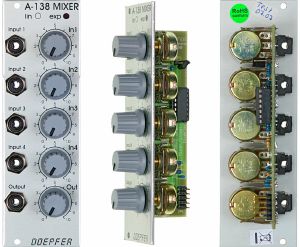
こんな商品も購入されています...
Doepfer A-138b 4-Channel Mixer Logarithmic Module (silver) (mixer synth module)
Cat: 577776 Rel: 29 Nov 17
Four channel mixer module - 8HP
Notes: Module A-138 is a four channel mixer, which can be used with either control voltages or audio signals. Each of the four inputs has an attenuator, and there's a master attenuator, so that the mixer can be used at the end of the audio chain, i.e. it can be used to interface directly with an external mixer, amplifier, etc.
The A-138b has potentiometers with logarithmic response, so is especially suitable for audio signal mixing.
… Read moreThe A-138b has potentiometers with logarithmic response, so is especially suitable for audio signal mixing.
1 in stock $66.55
Click for better price!
or call +44 20 7424 1960
quote 577776
quote 577776
こんな商品も購入されています...
Doepfer A-138d Crossfader/FX Insert Module (external/mixer synth module)
Cat: 716947 Rel: 29 Jan 19
Crossfader for two different A-100 signals, plus insert for external effects
Notes: The A-138d primarily is used for crossfading between two modular signals. On the other hand you can used it for inserting stompboxes or other effects into your modular system. Both the inputs and the mix output are available twice, like a mini-multiples e.g. for using the input signal also for other applications, kind of like a Thru.
Crossfader: With the crossfading control CF you blend manually between the inputs In 1 and In 2. The Mute switch allows for muting one of the two signals, independent on the crossfader position.
Effect insert: The signal at input In1 is emitted at the FX Send output and can be attenuated with the Atten. control because the modular system works with much higher levels.
The effect unit's output is inserted to the FX Return input socket and its level can be boosted with the Amp. control. The processed signal is available at the bottom in 2 socket.
Use the CF control to blend between the original signal and the effect signal and to mute switch for quick muting e.g. of the effect return signal.
… Read moreCrossfader: With the crossfading control CF you blend manually between the inputs In 1 and In 2. The Mute switch allows for muting one of the two signals, independent on the crossfader position.
Effect insert: The signal at input In1 is emitted at the FX Send output and can be attenuated with the Atten. control because the modular system works with much higher levels.
The effect unit's output is inserted to the FX Return input socket and its level can be boosted with the Amp. control. The processed signal is available at the bottom in 2 socket.
Use the CF control to blend between the original signal and the effect signal and to mute switch for quick muting e.g. of the effect return signal.
1 in stock $73.21
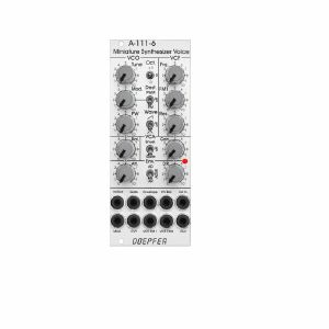
こんな商品も購入されています...
Doepfer A-111-6 Miniature Synthesiser Voice Slim Line Series Module (silver) (synth voice synth module)
Cat: 731937 Rel: 15 Nov 19
Complete miniature monophonic synthesiser module - 10HP
Notes: VCO:
- Tune: manual tune control (with an internal jumper the range can be set to ~ +/-1 half an octave or ~ +/-2.5 octaves)
- Oct: range switch -1 / 0 / +1 octave
- Mod: modulation depth (attenuator wired to the Mod. socket)
- Dest: switch that is used to address the modulation to frequency modulation (position FM) or pulsewidth modulation (positon PM), in centre positon no modulation
- PW: manual pulsewidth control for rectangle waveform, PW can be also modulated by the Mod. input as mentioned above
- Wave: waveform switch (sawtooth / off / triangle), the sum of the waveform chosen by this switch and the rectangle is fed into the VCF (to turn the rectangle off the PW control has to be set fully CCW or fully CW)
- 1V/Oct. (socket): external CV input for VCO frequency (1V/octave)
- Access to internal bus CV (via jumper, optional, please remove the bus jumper if this feature is not used to avoid unwanted frequency modulation as then the unused CV line of the bus works as a kind of antenna)
- Triangle core VCO, frequency range about 32Hz ... 8kHz
Balance unit:
- The balance unit is made of two VCAs which are controlled by the sum of manual Balance control and the balance CV input in the opposite direction.
- The audio input of VCA1 is hard-wired to the VCO output, audio input 2 is connected to the socket Ext.In.
- The output of the balance unit is used as audio input for the VCF
- Bal.: manual balance control, fully CCW the internal VCO is used, fully CW the external signal (Ext.In) is used, at centre position both signals have about the same level
- CV Bal.: CV input for balance (range about 0...+5V)
- Ext. In: external audio input for VCA2, about 5 Vpp level required for similar loudness as the internal VCO
- This socket is normalled to the internal VCO suboctave f/2 signal (rectangle with half the frequency), if no external signal is applied the suboctave signal is used as the second signal for the balance unit
VCF:
- 24 dB low pass
- Frq: manual frequency control
- FM1: frequency modulation depth (attenuator wired to the VCF FM1 socket, the socket is normalled to the internal Envelope signal and then FM1 controls the modulation depth of the internal envelope applied to the filter)
- FM2 (socket) : second CV input for VCF without attenuator (about 1V/octave), can be used e.g. for VCF tracking by connecting the same CV which is used also for the VCO frequency
- Res: manual resonance control (up to self oscillation)
- If the VCO is turned off (waveform switch = centre position, pulsewidth control = fully CCW or CW) and the VCF resonance is set to maximum the module can be used as a sine oscillator, the tracking at socket VCF FM2 is about 1V/octave (not as precise as the VCO but much better than most other filters)
- ~ 11 octaves frequency range (~ 10 Hz ... 20kHz)
VCA:
- Gain: manual amplitude control (initial gain), can be used to open the VCA without envelope signal
- VCA (switch): used to switch between gate and envelope as control signal for the VCA, in centre position the VCA is not controlled by envelope or gate
- Note: when gate is used the VCA is controlled directly by the gate signal (i.e. hard on/off), this may lead to clicking noise under certain conditions (especially with low VCO/VCF frequencies)
- Special control scale: exponential scale in the range from about -20dB to -80/90dB, linear scale from about -20dB to 0dB
- Remark: this special control scale results in a loudness behaviour that is a bit different from pure linear or exponential VCAs
- Out: audio output of the module (= VCA output)
Envelope:
- Gate (socket): Gate input (min. +5V), can be normalled to the bus gate signal by means of a jumper
- Att: manual control for Attack
- D/R: manual control for Decay/Release
- Env. (switch): used to switch between A/D, ADSR and A/R mode of the envelope generator, in centre position (ADSR) the sustain level is fixed to about 50%
- Envelope (socket): envelope output (about +10V)
- CVT (socket): CV input for time control, by means of two internal jumpers one can select which time parameters are controlled by the CVT input (e.g. A only or D/R only or A/D/R) and in which direction (i.e. if an increasing CVT shortens or stretches the time parameter in question)
- Envelope LED display
- Attack time range: ~ 1ms ... 5 sec (can be extended by using the CVT input)
- Decay/Release time range: ~ 1ms ... 15 sec (can be extended by using the CVT input)
… Read more- Tune: manual tune control (with an internal jumper the range can be set to ~ +/-1 half an octave or ~ +/-2.5 octaves)
- Oct: range switch -1 / 0 / +1 octave
- Mod: modulation depth (attenuator wired to the Mod. socket)
- Dest: switch that is used to address the modulation to frequency modulation (position FM) or pulsewidth modulation (positon PM), in centre positon no modulation
- PW: manual pulsewidth control for rectangle waveform, PW can be also modulated by the Mod. input as mentioned above
- Wave: waveform switch (sawtooth / off / triangle), the sum of the waveform chosen by this switch and the rectangle is fed into the VCF (to turn the rectangle off the PW control has to be set fully CCW or fully CW)
- 1V/Oct. (socket): external CV input for VCO frequency (1V/octave)
- Access to internal bus CV (via jumper, optional, please remove the bus jumper if this feature is not used to avoid unwanted frequency modulation as then the unused CV line of the bus works as a kind of antenna)
- Triangle core VCO, frequency range about 32Hz ... 8kHz
Balance unit:
- The balance unit is made of two VCAs which are controlled by the sum of manual Balance control and the balance CV input in the opposite direction.
- The audio input of VCA1 is hard-wired to the VCO output, audio input 2 is connected to the socket Ext.In.
- The output of the balance unit is used as audio input for the VCF
- Bal.: manual balance control, fully CCW the internal VCO is used, fully CW the external signal (Ext.In) is used, at centre position both signals have about the same level
- CV Bal.: CV input for balance (range about 0...+5V)
- Ext. In: external audio input for VCA2, about 5 Vpp level required for similar loudness as the internal VCO
- This socket is normalled to the internal VCO suboctave f/2 signal (rectangle with half the frequency), if no external signal is applied the suboctave signal is used as the second signal for the balance unit
VCF:
- 24 dB low pass
- Frq: manual frequency control
- FM1: frequency modulation depth (attenuator wired to the VCF FM1 socket, the socket is normalled to the internal Envelope signal and then FM1 controls the modulation depth of the internal envelope applied to the filter)
- FM2 (socket) : second CV input for VCF without attenuator (about 1V/octave), can be used e.g. for VCF tracking by connecting the same CV which is used also for the VCO frequency
- Res: manual resonance control (up to self oscillation)
- If the VCO is turned off (waveform switch = centre position, pulsewidth control = fully CCW or CW) and the VCF resonance is set to maximum the module can be used as a sine oscillator, the tracking at socket VCF FM2 is about 1V/octave (not as precise as the VCO but much better than most other filters)
- ~ 11 octaves frequency range (~ 10 Hz ... 20kHz)
VCA:
- Gain: manual amplitude control (initial gain), can be used to open the VCA without envelope signal
- VCA (switch): used to switch between gate and envelope as control signal for the VCA, in centre position the VCA is not controlled by envelope or gate
- Note: when gate is used the VCA is controlled directly by the gate signal (i.e. hard on/off), this may lead to clicking noise under certain conditions (especially with low VCO/VCF frequencies)
- Special control scale: exponential scale in the range from about -20dB to -80/90dB, linear scale from about -20dB to 0dB
- Remark: this special control scale results in a loudness behaviour that is a bit different from pure linear or exponential VCAs
- Out: audio output of the module (= VCA output)
Envelope:
- Gate (socket): Gate input (min. +5V), can be normalled to the bus gate signal by means of a jumper
- Att: manual control for Attack
- D/R: manual control for Decay/Release
- Env. (switch): used to switch between A/D, ADSR and A/R mode of the envelope generator, in centre position (ADSR) the sustain level is fixed to about 50%
- Envelope (socket): envelope output (about +10V)
- CVT (socket): CV input for time control, by means of two internal jumpers one can select which time parameters are controlled by the CVT input (e.g. A only or D/R only or A/D/R) and in which direction (i.e. if an increasing CVT shortens or stretches the time parameter in question)
- Envelope LED display
- Attack time range: ~ 1ms ... 5 sec (can be extended by using the CVT input)
- Decay/Release time range: ~ 1ms ... 15 sec (can be extended by using the CVT input)
1 in stock $191.33
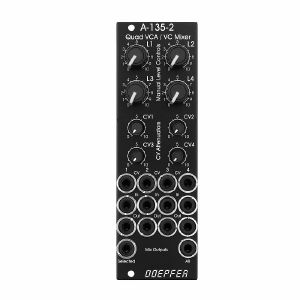
こんな商品も購入されています...
Doepfer A-135-2v Quad VCA & VC Mixer Vintage Edition Module (black) (modular synthesiser)
Cat: 790453 Rel: 30 Oct 20
Quad voltage controlled amplifier & mixer module - 8HP
Notes: A-135-2 is a miniature version of the A-135-1. Behind a front panel with 8 HP only four linear VCAs (voltage controlled amplifiers) and a voltage controlled mixer based on the VCAs are available.
Controls, In/Outputs and Functions of each VCA:
Level (manual control of the VCA amplification), small rubberized knob (L1...L4)
Control voltage input with associated attenuator (CV1...CV4), for the full VCA control range about 0...+5V control voltage are required (attenuator fully clockwise), for higher control voltages the attenuator is used, the attenuators are without knobs, just plastic shafts with white marker
Signal Input
Signal Output
All inputs and outputs are DC coupled. Consequently the VCAs can be used to process both audio and control voltages (e.g. to control the level of LFOs or envelopes)
The signal input is not equipped with an attenuator. But the VCAs can process all signals up to 15Vpp / -7.5...+7.5V without clipping. In case of higher levels an external attenuator is required (e.g. A-183-1).
The available amplification range is 0...1, the maximal amplification is 1 (i.e. it "clips" and remains at 1 even if the control voltage goes beyond the value that corresponds to amplification 1)
Functions of the voltage controlled mixers:
two outputs ("Selected" and "All")
Selected output: the ouput if a VCA is removed from this sum signal when a plug is inserted into the corresponding VCA output.
All output: sum of all VCA outputs, regardless of inserted plugs into the VCA outputs
The maximal amplification is about 0.6 to avoid clipping at the mixer outputs (otherwise the outputs may distort with 15Vpp signals at each signal input and full amplifications)
Special functions of the voltage controlled mixer (selectable by internal jumpers)
Dual Stereo VCA: In this case the control unit of VCA1 (L1 + CV1) affects also VCA3 and the control unit of VCA2 (L2 + CV2) affects also VCA4. The control units of VCA3 (L3 + CV3) and VCA4 (L4 +CV4) are out of operation.
Quad VCA: In this case the control unit of VCA1 (L1 + CV1) affects all four VCAs. The control units of VCA2, VCA3 and VCA4 are out of operation. In this mode the module has the same function as module A-132-2. That's why module A-132-2 will be discontinued.
Normalling of the signal inputs: by means of internal jumpers signal input 1 can be normalled to signal input 2, signal input 2 to signal input 3 and signal input 3 to signal input In 4. That way the same input signal can be distributed to four different channels by means of control voltages (e.g. quadrophonic distribution of audio signals). Suitable control voltage sources are e.g. A-144 (Morphing Controller) or A-143-9 (Quadrature LFO).
Additional technical specification for each VCA (based on the specifications of the VCA circuits CEM3360/AS3360 used in the module):
Crosstalk between VCAs: typ. - 80dB
Signal attenuation at 0V CV: typ. -70dB
Total harmonic distortion: typ. 1%
Control voltage feedthrough: max. 15mV
Width: 8 HP / 40.3 mm
Depth: 45 mm (measured from the rear side of the front panel)
Current: +40mA (+12V) / -40mA (-12V)
… Read moreControls, In/Outputs and Functions of each VCA:
Level (manual control of the VCA amplification), small rubberized knob (L1...L4)
Control voltage input with associated attenuator (CV1...CV4), for the full VCA control range about 0...+5V control voltage are required (attenuator fully clockwise), for higher control voltages the attenuator is used, the attenuators are without knobs, just plastic shafts with white marker
Signal Input
Signal Output
All inputs and outputs are DC coupled. Consequently the VCAs can be used to process both audio and control voltages (e.g. to control the level of LFOs or envelopes)
The signal input is not equipped with an attenuator. But the VCAs can process all signals up to 15Vpp / -7.5...+7.5V without clipping. In case of higher levels an external attenuator is required (e.g. A-183-1).
The available amplification range is 0...1, the maximal amplification is 1 (i.e. it "clips" and remains at 1 even if the control voltage goes beyond the value that corresponds to amplification 1)
Functions of the voltage controlled mixers:
two outputs ("Selected" and "All")
Selected output: the ouput if a VCA is removed from this sum signal when a plug is inserted into the corresponding VCA output.
All output: sum of all VCA outputs, regardless of inserted plugs into the VCA outputs
The maximal amplification is about 0.6 to avoid clipping at the mixer outputs (otherwise the outputs may distort with 15Vpp signals at each signal input and full amplifications)
Special functions of the voltage controlled mixer (selectable by internal jumpers)
Dual Stereo VCA: In this case the control unit of VCA1 (L1 + CV1) affects also VCA3 and the control unit of VCA2 (L2 + CV2) affects also VCA4. The control units of VCA3 (L3 + CV3) and VCA4 (L4 +CV4) are out of operation.
Quad VCA: In this case the control unit of VCA1 (L1 + CV1) affects all four VCAs. The control units of VCA2, VCA3 and VCA4 are out of operation. In this mode the module has the same function as module A-132-2. That's why module A-132-2 will be discontinued.
Normalling of the signal inputs: by means of internal jumpers signal input 1 can be normalled to signal input 2, signal input 2 to signal input 3 and signal input 3 to signal input In 4. That way the same input signal can be distributed to four different channels by means of control voltages (e.g. quadrophonic distribution of audio signals). Suitable control voltage sources are e.g. A-144 (Morphing Controller) or A-143-9 (Quadrature LFO).
Additional technical specification for each VCA (based on the specifications of the VCA circuits CEM3360/AS3360 used in the module):
Crosstalk between VCAs: typ. - 80dB
Signal attenuation at 0V CV: typ. -70dB
Total harmonic distortion: typ. 1%
Control voltage feedthrough: max. 15mV
Width: 8 HP / 40.3 mm
Depth: 45 mm (measured from the rear side of the front panel)
Current: +40mA (+12V) / -40mA (-12V)
1 in stock $142.00
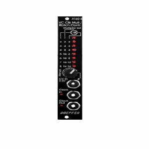
こんな商品も購入されています...
Doepfer A-160-5v Voltage Controlled Clock Multiplier & Ratcheting Controller Module (vintage edition) (synth module)
Cat: 745789 Rel: 10 Sep 19
Voltage-controlled clock multiplier with CV or manual control - 4HP
Notes: Module A-160-5 is a voltage controlled clock multiplier. The incoming clock signal (socket Clock In) is multiplied by a factor that depends upon the control voltage on socket CV In (0...+5V) and the position of the Mode switch. The multiplied clock signal is available at the socket Clock Out. According to the position of the Mode switch different clock multiplying factors are assigned to the control voltage. With 0V CV no clock output is generated. This state is indicated by "all LEDs off". With increasing CV integer factors (left position of the mode switch), power of two factors (middle position) or a mix of both (right position) are obtained. Nine LEDs are used to show the currently selected multiplying factor. In addition two LEDs are used to display the incoming and outgoing clock signal.
A manual control is used to adjust the clock multiplication factor manually without the need of an external control voltage. The voltage generated by this control ("Manual") is normalled to the CV In socket. As long as no plug is inserted into the CV In socket the clock multiplication factor is adjusted by means of the manual control knob and displayed by the LEDs. For dynamic applications (like the ratcheting function described below) the manually generated CV is overwritten by the external CV which has to be fed into the CV In socket.
The module can be used for all kind of clock multiplying applications. One important example is the generation of so-called ratcheting sequences. The band Tangerine Dream is famous for this kind of sequences. A normal sequencer generates only one gate signal per step. A ratcheting sequence may have also more than one gate pulses per step. This function can be obtained by using the A-160-5: one CV output of the sequencer is used to define the number of gate pulses per step. If the control of the step in question is fully CCW the generated CV is 0V and no gate signal is generated (mute of the step). When the control of the step in question is turned clockwise one, two or more gate pulses are generated depending upon the position of the mode switch and the voltage generated by the CV at this step.
Technical note: Due to the nature of clock multiplying it takes a few input clock pulses until the clock output is stable. One has to average a few input clock pulses to generate the multiplied clock output signal. Even when the input clock frequency changes it will take a few cycles until the output clock signal is correct as the module cannot foresee the future of the clock input signal. The generated clock output signal is derived from the last few cycles of the clock input signal. Consequently the module should be driven only by a clock signal with constant or slowly changing frequency.
… Read moreA manual control is used to adjust the clock multiplication factor manually without the need of an external control voltage. The voltage generated by this control ("Manual") is normalled to the CV In socket. As long as no plug is inserted into the CV In socket the clock multiplication factor is adjusted by means of the manual control knob and displayed by the LEDs. For dynamic applications (like the ratcheting function described below) the manually generated CV is overwritten by the external CV which has to be fed into the CV In socket.
The module can be used for all kind of clock multiplying applications. One important example is the generation of so-called ratcheting sequences. The band Tangerine Dream is famous for this kind of sequences. A normal sequencer generates only one gate signal per step. A ratcheting sequence may have also more than one gate pulses per step. This function can be obtained by using the A-160-5: one CV output of the sequencer is used to define the number of gate pulses per step. If the control of the step in question is fully CCW the generated CV is 0V and no gate signal is generated (mute of the step). When the control of the step in question is turned clockwise one, two or more gate pulses are generated depending upon the position of the mode switch and the voltage generated by the CV at this step.
Technical note: Due to the nature of clock multiplying it takes a few input clock pulses until the clock output is stable. One has to average a few input clock pulses to generate the multiplied clock output signal. Even when the input clock frequency changes it will take a few cycles until the output clock signal is correct as the module cannot foresee the future of the clock input signal. The generated clock output signal is derived from the last few cycles of the clock input signal. Consequently the module should be driven only by a clock signal with constant or slowly changing frequency.
1 in stock $116.48
Click for better price!
or call +44 20 7424 1960
quote 745789
quote 745789
こんな商品も購入されています...
Doepfer A-134-2 Dual Voltage Controlled Crossfader Module (VCA/dual/stereo/panning synth module)
Cat: 716922 Rel: 29 Jan 19
Dual crossfader module for voltage controlled morphing between two audio or CV signals
Notes: Module A-134-2 contains two identical voltage controlled crossfader units.
Each unit has two voltage controlled amplifiers (VCAs) with opposite control behaviour available. The outputs of the two VCAs are mixed together to obtain a common output. The behaviour of the control voltage inputs can be chosen with an internal jumper:
Symmetrical mode: If the corresponding jumper is not set both VCAs of the crossfader have the same 50% amplification with zero CV. If the applied CV becomes positive the amplification of VCA1 decreases and those of VCA2 increases in the same way. A negative CV has the opposite result. The CV voltage range to obtain the maximum/minimum positions of the crossfader is about -2.5....+2.5V. This mode is useful for bidirectional (i.e. positive and negative) control voltages, for example LFO or joy stick (adjusted to 0V CV in centre position).
Asymmetrical mode: If the corresponding jumper is set VCA2 is fully closed and VCA1 has full 100% amplification with zero CV. If the applied CV becomes positive the amplification of VCA1 decreases and those of VCA2 increases in the same way. The CV voltage range to obtain the maximum/minimum positions of the crossfader is about 0...+5V. A negative CV has no function in this mode. This mode is useful for unidirectional (i.e. only positive) control voltages, for example ADSR, ribbon controller or Theremin control voltage.
The CV input of the upper unit (CV1) is normalled to the CV input of the lower unit (CV2). I.e. if no plug is inserted to CV2 the CV input of the upper unit (CV1) also controls the lower unit.
The second signal input of the upper unit (In1B) is normalled to the first signal input of the lower unit (In2A). I.e. if no plug is inserted into In2A the signal In1B is used as the first signal input of the second unit.
As the inputs and outputs are DC coupled the module can be used for both audio and control voltage signal processing.
… Read moreEach unit has two voltage controlled amplifiers (VCAs) with opposite control behaviour available. The outputs of the two VCAs are mixed together to obtain a common output. The behaviour of the control voltage inputs can be chosen with an internal jumper:
Symmetrical mode: If the corresponding jumper is not set both VCAs of the crossfader have the same 50% amplification with zero CV. If the applied CV becomes positive the amplification of VCA1 decreases and those of VCA2 increases in the same way. A negative CV has the opposite result. The CV voltage range to obtain the maximum/minimum positions of the crossfader is about -2.5....+2.5V. This mode is useful for bidirectional (i.e. positive and negative) control voltages, for example LFO or joy stick (adjusted to 0V CV in centre position).
Asymmetrical mode: If the corresponding jumper is set VCA2 is fully closed and VCA1 has full 100% amplification with zero CV. If the applied CV becomes positive the amplification of VCA1 decreases and those of VCA2 increases in the same way. The CV voltage range to obtain the maximum/minimum positions of the crossfader is about 0...+5V. A negative CV has no function in this mode. This mode is useful for unidirectional (i.e. only positive) control voltages, for example ADSR, ribbon controller or Theremin control voltage.
The CV input of the upper unit (CV1) is normalled to the CV input of the lower unit (CV2). I.e. if no plug is inserted to CV2 the CV input of the upper unit (CV1) also controls the lower unit.
The second signal input of the upper unit (In1B) is normalled to the first signal input of the lower unit (In2A). I.e. if no plug is inserted into In2A the signal In1B is used as the first signal input of the second unit.
As the inputs and outputs are DC coupled the module can be used for both audio and control voltage signal processing.
1 in stock $77.65
Click for better price!
or call +44 20 7424 1960
quote 716922
quote 716922
こんな商品も購入されています...
Doepfer A-101-2 LPG Vactrol Low Pass Gate Module (silver) (low pass gate synth module)
Cat: 682314 Rel: 26 Mar 18
Vactrol based combination of resonant 12dB lowpass filter and/or VCA - inspired by the Buchla 292
Notes: A Low Pass Gate (LPG) can be a low pass filter, a VCA or a combination of both. This means both the harmonic content and volume can be controlled simultaneously which resembles the behaviour of many instruments: the louder, the more harmonics.
The A-101-2's mode of operation is set with a switch: left position is low pass, right is VCA and the combo mode is in the centre. Alternatively, you can activate the modes with gate signals which is the reason for two gate inputs; this is very interesting in combination with clock dividers or trigger sequencers.
- Gate 1 high & gate 2 low = low pass mode
- Gate 1 low & gate 2 high = VCA mode
- Both Gate 1 & 2 high = combo mode
The A-101-2 has an aggressive sound, compared to other LPGs and its resonance goes up to self-oscillation which not many LPGs offer. The oscillation is rather dirty and far from being a sine wave.
3U Eurorack module, 8HP wide, 50mm deep.
… Read moreThe A-101-2's mode of operation is set with a switch: left position is low pass, right is VCA and the combo mode is in the centre. Alternatively, you can activate the modes with gate signals which is the reason for two gate inputs; this is very interesting in combination with clock dividers or trigger sequencers.
- Gate 1 high & gate 2 low = low pass mode
- Gate 1 low & gate 2 high = VCA mode
- Both Gate 1 & 2 high = combo mode
The A-101-2 has an aggressive sound, compared to other LPGs and its resonance goes up to self-oscillation which not many LPGs offer. The oscillation is rather dirty and far from being a sine wave.
3U Eurorack module, 8HP wide, 50mm deep.
1 in stock $104.28
Click for better price!
or call +44 20 7424 1960
quote 682314
quote 682314
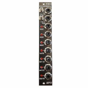
こんな商品も購入されています...
Doepfer A-160-2v Clock/Trigger Divider II Module (vintage edition) (clock modulator synth module)
Cat: 864696 Rel: 14 Mar 22
Module A-160-2 is an enhanced version of the standard clock divider A-160.
Notes: Module A-160-2V is an enhanced version of the standard clock divider A-160. The module is a frequency divider for clock/trigger/gate signals, designed to be a source of lower frequencies, particularly for rhythm uses.
The Clock input will take any digital signal from, eg., an LFO, MIDI sync, or the gate from a MIDI-CV interface. At the outputs, you have access to three sets of seven different sub-divided clock signals, from half the clock frequency down to 1/128. The low/high levels of the output signals are 0V and about +10V.
The A-160-2V also has a reset input. Whenever a reset signal is sensed, all outputs are set to certain levels which depend upon the selected mode.
HP : 4
… Read moreThe Clock input will take any digital signal from, eg., an LFO, MIDI sync, or the gate from a MIDI-CV interface. At the outputs, you have access to three sets of seven different sub-divided clock signals, from half the clock frequency down to 1/128. The low/high levels of the output signals are 0V and about +10V.
The A-160-2V also has a reset input. Whenever a reset signal is sensed, all outputs are set to certain levels which depend upon the selected mode.
HP : 4
4 in stock $115.37
Click for better price!
or call +44 20 7424 1960
quote 864696
quote 864696
こんな商品も購入されています...
Doepfer A-192-2 Dual CV & Gate To MIDI & USB Interface Module (CV to MIDI synth module)
Cat: 755414 Rel: 20 Nov 19
Two CV/Gate to MIDI/USB interfaces, each with a common 1V/Oct CV transpose input - 10HP
Notes: Module A-192-2 contains two independent CV/Gate-to-Midi/USB interfaces. For each of the two sub-units these inputs are available:
- Gate Input (min. +5V)
- CVN Input (defines the Midi note number), 1V/octave standard, range 0...+10V (i.e. 10 octaves)
- CVV Input (defines the velocity value assigned to the Midi note message), can be used alternatively for Midi volume (CC#7), range 0...+5V
- CVC Input (free assignable to any Midi control change number), range 0...+5V
For both sub-units a common CV Transpose input is available (1V/octave, range 0...+10V). The voltage applied to this input is added internally to CVN before the Midi note number is generated. It can be used e.g. to transpose two sequences simultaneously by one voltage.
How it works:
Whenever the rising edge of the Gate input is recognized a Midi note on message is generated. The note number corresponds to the sum of the voltages applied to the CVN input and the common CV Transpose Input that is present at the rising edge of the gate signal.
… Read more- Gate Input (min. +5V)
- CVN Input (defines the Midi note number), 1V/octave standard, range 0...+10V (i.e. 10 octaves)
- CVV Input (defines the velocity value assigned to the Midi note message), can be used alternatively for Midi volume (CC#7), range 0...+5V
- CVC Input (free assignable to any Midi control change number), range 0...+5V
For both sub-units a common CV Transpose input is available (1V/octave, range 0...+10V). The voltage applied to this input is added internally to CVN before the Midi note number is generated. It can be used e.g. to transpose two sequences simultaneously by one voltage.
How it works:
Whenever the rising edge of the Gate input is recognized a Midi note on message is generated. The note number corresponds to the sum of the voltages applied to the CVN input and the common CV Transpose Input that is present at the rising edge of the gate signal.
2 in stock $133.12
こんな商品も購入されています...
Doepfer A-160-5 Voltage Controlled Clock Multiplier & Ratcheting Controller Module (silver) (clock modulator synth module)
Cat: 745787 Rel: 10 Sep 19
Voltage-controlled clock multiplier with CV or manual control - 4HP
Notes: Module A-160-5 is a voltage controlled clock multiplier. The incoming clock signal (socket Clock In) is multiplied by a factor that depends upon the control voltage on socket CV In (0...+5V) and the position of the Mode switch. The multiplied clock signal is available at the socket Clock Out. According to the position of the Mode switch different clock multiplying factors are assigned to the control voltage. With 0V CV no clock output is generated. This state is indicated by "all LEDs off". With increasing CV integer factors (left position of the mode switch), power of two factors (middle position) or a mix of both (right position) are obtained. Nine LEDs are used to show the currently selected multiplying factor. In addition two LEDs are used to display the incoming and outgoing clock signal.
A manual control is used to adjust the clock multiplication factor manually without the need of an external control voltage. The voltage generated by this control ("Manual") is normalled to the CV In socket. As long as no plug is inserted into the CV In socket the clock multiplication factor is adjusted by means of the manual control knob and displayed by the LEDs. For dynamic applications (like the ratcheting function described below) the manually generated CV is overwritten by the external CV which has to be fed into the CV In socket.
The module can be used for all kind of clock multiplying applications. One important example is the generation of so-called ratcheting sequences. The band Tangerine Dream is famous for this kind of sequences. A normal sequencer generates only one gate signal per step. A ratcheting sequence may have also more than one gate pulses per step. This function can be obtained by using the A-160-5: one CV output of the sequencer is used to define the number of gate pulses per step. If the control of the step in question is fully CCW the generated CV is 0V and no gate signal is generated (mute of the step). When the control of the step in question is turned clockwise one, two or more gate pulses are generated depending upon the position of the mode switch and the voltage generated by the CV at this step.
Technical note: Due to the nature of clock multiplying it takes a few input clock pulses until the clock output is stable. One has to average a few input clock pulses to generate the multiplied clock output signal. Even when the input clock frequency changes it will take a few cycles until the output clock signal is correct as the module cannot foresee the future of the clock input signal. The generated clock output signal is derived from the last few cycles of the clock input signal. Consequently the module should be driven only by a clock signal with constant or slowly changing frequency.
… Read moreA manual control is used to adjust the clock multiplication factor manually without the need of an external control voltage. The voltage generated by this control ("Manual") is normalled to the CV In socket. As long as no plug is inserted into the CV In socket the clock multiplication factor is adjusted by means of the manual control knob and displayed by the LEDs. For dynamic applications (like the ratcheting function described below) the manually generated CV is overwritten by the external CV which has to be fed into the CV In socket.
The module can be used for all kind of clock multiplying applications. One important example is the generation of so-called ratcheting sequences. The band Tangerine Dream is famous for this kind of sequences. A normal sequencer generates only one gate signal per step. A ratcheting sequence may have also more than one gate pulses per step. This function can be obtained by using the A-160-5: one CV output of the sequencer is used to define the number of gate pulses per step. If the control of the step in question is fully CCW the generated CV is 0V and no gate signal is generated (mute of the step). When the control of the step in question is turned clockwise one, two or more gate pulses are generated depending upon the position of the mode switch and the voltage generated by the CV at this step.
Technical note: Due to the nature of clock multiplying it takes a few input clock pulses until the clock output is stable. One has to average a few input clock pulses to generate the multiplied clock output signal. Even when the input clock frequency changes it will take a few cycles until the output clock signal is correct as the module cannot foresee the future of the clock input signal. The generated clock output signal is derived from the last few cycles of the clock input signal. Consequently the module should be driven only by a clock signal with constant or slowly changing frequency.
1 in stock $107.61
Click for better price!
or call +44 20 7424 1960
quote 745787
quote 745787
こんな商品も購入されています...
Doepfer A-111-4 Quad Precision VCO Module (silver) (oscillator synth module)
Cat: 671550 Rel: 29 Nov 17
Quad precision voltage contolled oscillator module - 18HP
Notes: A-111-4 contains four precision VCOs and has individual controls, inputs and outputs for each VCO available as well as a common control and output unit. After all the A-111-4 is very similar to four A-111-3 without LFO mode but built in output mixers for the three waveforms, and a master unit for all four VCOs.
Controls, inputs and outputs for each of the four VCOs:
- 1V/Octave CV input
- Octave switch (+1 / 0 / -1 octave)
- Tune control (range internally adjustable by jumpers: ~ 2 semitones / ~ 1 octave / ~ 4 octaves)
- Modulation CV input
- Modulation destination:
- Upper position: exponential frequency modulation (XM)lower position: linear frequency modulation (LM) or pulsewidth modulation of the rectangle (PM), selectable via internal jumper
- Frequency Modulation (FM) or Pulsewidth Modulation of the rectangle (PWM)
- Modulation intensity
- Triangle output
- Sawtooth output
- Rectangle output (about 50% without external PWM)
- Sync input (hard or soft sync internally selectable via jumper, CEM3340 hard sync type)
- Min. 10 octaves range (with appropriate external CV)
- CEM3340 based VCO (triangle core)
- Each VCO has it's own separate internal +/- power supply for each for best stability and the prevention of unwanted synchronisation of the VCOs
Controls, inputs and outputs of the master section:
- 1V/Octave CV input
- Octave switch (+1 / 0 / -1 octave)
- Tune control (range internally adjustable by jumpers: 2 semitones / 1 octave / 4 octaves)
- Frequency Modulation CV input (FM)
- FM intensity
- Triangle sum output
- Sawtooth sum output
- Rectangle sum output
- As soon as the single waveform output of a VCO is patched this waveform of the VCO in question is removed from the sum (this function can be turned off for each single output socket by means of solder bridges on the pc board, i.e. the sum contains then all signals independent of the patching of the single output)
- CV output (outputs the sum CV that is used to control all four VCOs)
- Bus CV (selectable via jumper)
Typical applications:
- Fat sounding monophonic VCO with the possibility to adjust any intervals
- Paraphonic patches in combination with the polyphonic CV interface A-190-5 (all four VCOs processed by one VCF/VCA)
- Full polyphonic patches in combination with the polyphonic CV interface A-190-5 and four complete VCF/VCA sections
- Complex VCO patches with up to four VCOs by means of the frequency modulation features (exponential an linear) and the sync functions
… Read moreControls, inputs and outputs for each of the four VCOs:
- 1V/Octave CV input
- Octave switch (+1 / 0 / -1 octave)
- Tune control (range internally adjustable by jumpers: ~ 2 semitones / ~ 1 octave / ~ 4 octaves)
- Modulation CV input
- Modulation destination:
- Upper position: exponential frequency modulation (XM)lower position: linear frequency modulation (LM) or pulsewidth modulation of the rectangle (PM), selectable via internal jumper
- Frequency Modulation (FM) or Pulsewidth Modulation of the rectangle (PWM)
- Modulation intensity
- Triangle output
- Sawtooth output
- Rectangle output (about 50% without external PWM)
- Sync input (hard or soft sync internally selectable via jumper, CEM3340 hard sync type)
- Min. 10 octaves range (with appropriate external CV)
- CEM3340 based VCO (triangle core)
- Each VCO has it's own separate internal +/- power supply for each for best stability and the prevention of unwanted synchronisation of the VCOs
Controls, inputs and outputs of the master section:
- 1V/Octave CV input
- Octave switch (+1 / 0 / -1 octave)
- Tune control (range internally adjustable by jumpers: 2 semitones / 1 octave / 4 octaves)
- Frequency Modulation CV input (FM)
- FM intensity
- Triangle sum output
- Sawtooth sum output
- Rectangle sum output
- As soon as the single waveform output of a VCO is patched this waveform of the VCO in question is removed from the sum (this function can be turned off for each single output socket by means of solder bridges on the pc board, i.e. the sum contains then all signals independent of the patching of the single output)
- CV output (outputs the sum CV that is used to control all four VCOs)
- Bus CV (selectable via jumper)
Typical applications:
- Fat sounding monophonic VCO with the possibility to adjust any intervals
- Paraphonic patches in combination with the polyphonic CV interface A-190-5 (all four VCOs processed by one VCF/VCA)
- Full polyphonic patches in combination with the polyphonic CV interface A-190-5 and four complete VCF/VCA sections
- Complex VCO patches with up to four VCOs by means of the frequency modulation features (exponential an linear) and the sync functions
1 in stock $384.96
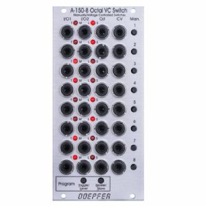
こんな商品も購入されています...
Doepfer A-150-8 Octal VC Switch Manually/Voltage Controlled Switch Module (switch synth module)
Cat: 671556 Rel: 29 Nov 17
Manually or voltage controlled switch module - 12HP
Notes: Module A-150-8 contains eight manually/voltage controlled switches. Each of the eight switches has a manual control button (Man.), a control voltage input (CV), a common Out / Input (O/I), and two In / Outputs (I/O1, I/O2). The switches are bi-directional, i.e. they can work in both directions, so can connect one input to either of two outputs, or either of two inputs to one output. Two LEDs show which in / output is active (i.e. which is connected to the common out / input). In addition, the LEDs are used for the programming of the module:
For each unit the operating mode can be selected: Toggle or Level controlled. In Toggle mode the rising edge of the CV input or operating the manual control button changes the state of the switch. In Level mode the switch state is defined by the voltage applied to the CV input (low voltage = I/O1, high voltage = I/O2) or by the state of the manual control button (not pressed = I/O1, pressed = I/O2). The modes are programmed very easily: Operating the Toggle/Level button of the program section displays the current state of each switch with the LEDs: left LED on = Toggle mode, right LED on = Level mode. Operating the manual control button of the switch in question changes the toggle/level mode while the Toggle/Level button of the program section is operated. During the programming patched CV signals may have to be removed as the CV signals would interfere with the manual operating buttons during the programming process.
In addition, it's possible to define master/slave groups. In such a group the upper unit (= master) controls also the state of the following switches provided that they are defined as slaves. Master/slave programming is also very simple: Operating the Master/Slave button of the program section displays the current state of each switch with the LEDs: left LED on = Master, right LED on = Slave.
When all 8 units are defined as master all switches are independent from each other. If for example the sequence is MSSSMSMS the control unit of the first switch also controls the switches 2, 3 and 4. The control unit of switch 5 also controls the switch 6, and the control unit of switch 7 also controls the switch 8. The current states of the slave switches are overwritten by the state of the master switch.
Technical note: To protect the electronic switches in case of an unsuitable patch (e.g. connection of two outputs) a 1k protection resistor is inserted into the O/I line of each switch. If control voltages used for VCOs are switched this may cause a small voltage drop and lead to undesired audible detuning. For this application we recommend to insert a CV buffer between A-150-8 and the VCO(s), e.g. the Buffered Multiple A-180-3 or the Precision Adder A-185-2. Integrating the buffers into the module A-150-8 was not possible because this would ruin the bidirectionality of the switches.
Width: 12 HP / 60.6 mm
Depth: 55 mm (measured from the rear side of the front panel)
Current: +40mA (+12V) / -5mA (-12V)
… Read moreFor each unit the operating mode can be selected: Toggle or Level controlled. In Toggle mode the rising edge of the CV input or operating the manual control button changes the state of the switch. In Level mode the switch state is defined by the voltage applied to the CV input (low voltage = I/O1, high voltage = I/O2) or by the state of the manual control button (not pressed = I/O1, pressed = I/O2). The modes are programmed very easily: Operating the Toggle/Level button of the program section displays the current state of each switch with the LEDs: left LED on = Toggle mode, right LED on = Level mode. Operating the manual control button of the switch in question changes the toggle/level mode while the Toggle/Level button of the program section is operated. During the programming patched CV signals may have to be removed as the CV signals would interfere with the manual operating buttons during the programming process.
In addition, it's possible to define master/slave groups. In such a group the upper unit (= master) controls also the state of the following switches provided that they are defined as slaves. Master/slave programming is also very simple: Operating the Master/Slave button of the program section displays the current state of each switch with the LEDs: left LED on = Master, right LED on = Slave.
When all 8 units are defined as master all switches are independent from each other. If for example the sequence is MSSSMSMS the control unit of the first switch also controls the switches 2, 3 and 4. The control unit of switch 5 also controls the switch 6, and the control unit of switch 7 also controls the switch 8. The current states of the slave switches are overwritten by the state of the master switch.
Technical note: To protect the electronic switches in case of an unsuitable patch (e.g. connection of two outputs) a 1k protection resistor is inserted into the O/I line of each switch. If control voltages used for VCOs are switched this may cause a small voltage drop and lead to undesired audible detuning. For this application we recommend to insert a CV buffer between A-150-8 and the VCO(s), e.g. the Buffered Multiple A-180-3 or the Precision Adder A-185-2. Integrating the buffers into the module A-150-8 was not possible because this would ruin the bidirectionality of the switches.
Width: 12 HP / 60.6 mm
Depth: 55 mm (measured from the rear side of the front panel)
Current: +40mA (+12V) / -5mA (-12V)
1 in stock $172.19
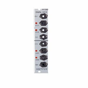
こんな商品も購入されています...
Doepfer A-150 Dual Voltage Controlled Switch Module (silver) (switch synth module)
Cat: 745778 Rel: 10 Sep 19
Two independent voltage controlled switches in one module - 4HP
Notes: Module A-150-1 (Dual VCS) contains two separate voltage-controlled switches.
Each switch has a control voltage input, a common Out / Input, and two In / Outputs. The switches are bi-directional: they can work in both directions, so can connect one input to either of two outputs, or either of two inputs to one output. Voltages in the range -8V...+8V at the O/I resp. I/O sockets can be processed by the module.
Two LEDs show which in / output is active (i.e. which is connected to the common out / input).
… Read moreEach switch has a control voltage input, a common Out / Input, and two In / Outputs. The switches are bi-directional: they can work in both directions, so can connect one input to either of two outputs, or either of two inputs to one output. Voltages in the range -8V...+8V at the O/I resp. I/O sockets can be processed by the module.
Two LEDs show which in / output is active (i.e. which is connected to the common out / input).
1 in stock $72.10
Click for better price!
or call +44 20 7424 1960
quote 745778
quote 745778
こんな商品も購入されています...
Doepfer A-108 6/12/24/48dB Low Pass Filter Module (filter synth module)
Cat: 692510 Rel: 19 Jun 18
Classic Moog voltage-controlled lowpass filter - 12HP
Notes: Module A-108 is a completely new voltage-controlled low pass filter based on the well-known transistor ladder (Moog ladder). The module has internally an 8-stage low pass filter with different slopes available: 6, 12, 18, 24, 30, 36, 42 and 48 dB per octave. In addition, it features a band pass output (i.e. band pass with transistor ladder). In the factory, the 4 low pass outputs of the A-108 are internally connected to the filter stages 6, 12, 24 and 48dB.
Resonance (Emphasis or Q) can be adjusted manually right up to self-oscillation, in which case the filter will behave like a sine wave oscillator. The A-108 features an external feedback input that enables the insertion of additional modules into the feedback path (e.g. VCA for voltage-controlled resonance or phaser/frequency shifter for phase/frequency shifting effects). The socket is normalized and internally connected to the 48dB low pass output if no cable is inserted into the feedback socket.
The frequency can be adjusted manually, or by voltage control. Three CV inputs (CV1, CV2, CV3) are available. CV2 and CV3 are equipped with attenuators.
The filter audio input is very sensitive so that distortion - if desired - is possible even with normal A-100 levels (e.g. VCO output). Self-oscillation will break off at high distortion levels as the internal feedback signal is drown out by the distorted audio signal. This feature may intentionally be used to create new sounds.
In combination with the Voltage Controlled Mixer A-135 and the Morphing Controller A-144 a filter with voltage-controlled slope can be realized (i.e. controlling the slope from 6dB to 48dB via CV).
… Read moreResonance (Emphasis or Q) can be adjusted manually right up to self-oscillation, in which case the filter will behave like a sine wave oscillator. The A-108 features an external feedback input that enables the insertion of additional modules into the feedback path (e.g. VCA for voltage-controlled resonance or phaser/frequency shifter for phase/frequency shifting effects). The socket is normalized and internally connected to the 48dB low pass output if no cable is inserted into the feedback socket.
The frequency can be adjusted manually, or by voltage control. Three CV inputs (CV1, CV2, CV3) are available. CV2 and CV3 are equipped with attenuators.
The filter audio input is very sensitive so that distortion - if desired - is possible even with normal A-100 levels (e.g. VCO output). Self-oscillation will break off at high distortion levels as the internal feedback signal is drown out by the distorted audio signal. This feature may intentionally be used to create new sounds.
In combination with the Voltage Controlled Mixer A-135 and the Morphing Controller A-144 a filter with voltage-controlled slope can be realized (i.e. controlling the slope from 6dB to 48dB via CV).
1 in stock $151.85
こんな商品も購入されています...
Doepfer A-101-8 Photo Phasing 8-Stage Phase Shifter Module (silver) (phase shifter/effect synth module)
Cat: 945411 Rel: 13 Jun 23
An eight stage phase shifter module in 4HP.
Notes: Module A-101-8 is a 8-stage phase shifter which uses light-sensitive resistors (LDR) and is a replica of the Compact Phasing A manufactured by the company Schulte in the seventies. The actual phasing circuit is identical to the historic model. Only the illumination control of the LDRs is different: the A-101-8 uses LEDs to illuminate the LDRs, the historic model used incandescent miniature lamps. And the A-101-8 has no built-in LFO but can be controlled by any external control voltage source (e.g. LFO, ADSR, random, Theremin, ribbon controller, sequencer, midi). The phasing offset (i.e. the base value for the phase shifting) and the modulation depth of the external control signal can be adjusted separately. The Compact Phasing A had no offset control but only a depth control for the built-in LFO. Feedback and mixing ratio of the output signal are set by two controls. The audio input is equipped with an attenuator. The module has two audio outputs available (same as the historic model) and a visual display of the phase shifting.
The module has these controls and in/outputs available:
Control Man. : manual control of the phase shift offset (base value)
Control CV: attenuator for the signal applied to the CV socket
Control Feedb.: Feedback or Resonance (similar function as filter resonance/feedback/emphasis)
Control Mix: sets the mixing ratio between original and phase shift signal appearing at output 1
fully CCW: only the modified input signal appears at output 1 (see note below *)
center: a mixture between the modified input signal and the phase shift signal appears at output 1, that's the standard position for the classical phasing effect
fully CW: the pure phase shifted signal appears at output 1 (e.g. for vibrato effects)
Control Input Level: attenuator for signal applied to the In socket
Socket In: audio input
Socket CV: control voltage input
Socket Out 1: audio output 1 (mix signal)
Socket Out 2: audio output 2 (modified input signal)
LED: visual control of the phase shift
The module has some peculiarities (same as the historic model):
The input signal is processed at first by a pre-stage which outputs a "modified" input signal (*). This signal is not processed by the phase shift stages but is affected by the feedback setting. Only when feedback is set to zero this signal is identical to the input signal. Otherwise it contains feedback components.
This signal is output on socket Out 2.
When both output sockets Out 1 and Out 2 are used as stereo channels one obtains a spatial stereo sound effect.
The same signals is also used for the CCW position of the mix control. With mix control fully CCW the unmodified signal appears only if the feedback control is set to zero. Otherwise it contains feedback components.
The historic model had two audio inputs: one 5-pin DIN socket and a 1/4" jack socket. The DIN socket was intended for high-level line signals. When the 1/4" jack socket was used the amplification of the pre-stage increased by about 100. The 1/4" jack socket was intended for low level signals (e.g. electric guitars or microphones). For this feature the A-101-8 has an internal jumper that can be used to increase the amplification. As long as the module is used within the A-100 system usually the lower amplification is used to avoid distortion.
The 8 photo resistors and LEDs are assembled within an small lighproof box. In addition the pc boards are made of lighproof black material to avoid interfering light from other modules or the bus board.
Dimensions
4 HP
45 mm deep
Current Draw
30 mA +12V
30 mA -12V
… Read moreThe module has these controls and in/outputs available:
Control Man. : manual control of the phase shift offset (base value)
Control CV: attenuator for the signal applied to the CV socket
Control Feedb.: Feedback or Resonance (similar function as filter resonance/feedback/emphasis)
Control Mix: sets the mixing ratio between original and phase shift signal appearing at output 1
fully CCW: only the modified input signal appears at output 1 (see note below *)
center: a mixture between the modified input signal and the phase shift signal appears at output 1, that's the standard position for the classical phasing effect
fully CW: the pure phase shifted signal appears at output 1 (e.g. for vibrato effects)
Control Input Level: attenuator for signal applied to the In socket
Socket In: audio input
Socket CV: control voltage input
Socket Out 1: audio output 1 (mix signal)
Socket Out 2: audio output 2 (modified input signal)
LED: visual control of the phase shift
The module has some peculiarities (same as the historic model):
The input signal is processed at first by a pre-stage which outputs a "modified" input signal (*). This signal is not processed by the phase shift stages but is affected by the feedback setting. Only when feedback is set to zero this signal is identical to the input signal. Otherwise it contains feedback components.
This signal is output on socket Out 2.
When both output sockets Out 1 and Out 2 are used as stereo channels one obtains a spatial stereo sound effect.
The same signals is also used for the CCW position of the mix control. With mix control fully CCW the unmodified signal appears only if the feedback control is set to zero. Otherwise it contains feedback components.
The historic model had two audio inputs: one 5-pin DIN socket and a 1/4" jack socket. The DIN socket was intended for high-level line signals. When the 1/4" jack socket was used the amplification of the pre-stage increased by about 100. The 1/4" jack socket was intended for low level signals (e.g. electric guitars or microphones). For this feature the A-101-8 has an internal jumper that can be used to increase the amplification. As long as the module is used within the A-100 system usually the lower amplification is used to avoid distortion.
The 8 photo resistors and LEDs are assembled within an small lighproof box. In addition the pc boards are made of lighproof black material to avoid interfering light from other modules or the bus board.
Dimensions
4 HP
45 mm deep
Current Draw
30 mA +12V
30 mA -12V
4 in stock $109.83
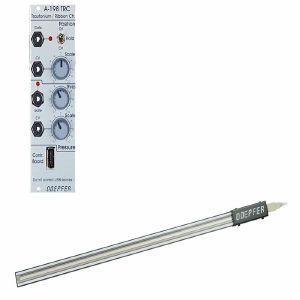
こんな商品も購入されています...
Doepfer A-198 TRC Trautonium Manual/Ribbon Controller Module (controller synth module)
Cat: 755418 Rel: 28 Nov 19
A-198 module with versatile ribbon controller
Notes: Module A-198 is a Trautonium Manual resp. Ribbon Controller. The controlling element of the A-198 is a linear position sensor (length about 50 cm) that has available a pressure sensor too.
Touching the sensor with a finger generates a control voltage CV1 that is proportional to the position of the finger. The scale (i.e. the relation between position difference and voltage difference) is adjustable with a potentiometer at the front panel. A hold switch is used to determine if the CV voltage is held after removing the finger (hold = on) or if the CV voltage jumps to 0V (hold = off). In the last case (hold = off) a gate signal is derived from the CV voltage whenever a finger touches the sensor (e.g. for triggering an envelope generator).
A sensitive pressure sensor located below the position sensor generates a second control voltage CV2 that increases with higher pressure of the finger. Even for CV2 the scale is adjustable. A second gate signal is triggered as soon as the pressure exceeds a certain value. The gate threshold is adjustable at the front panel.
The sensors are located in a separate metal frame (length about 600 mm, width about 30 mm, height about 18 mm, weight: about 900 g, colour: silver-grey). The connection between the module and the sensor frame is made by a 4 pin cable (same as used for USB connections).
Typical applications:
- Trautonium manual, the string is replaced by the position sensor that is much easier to use and cheaper than the string. In combination with the Subharmonic Oscillator A-113, the Trautonium Filter A-104 and some auxiliary modules a complete Trautonium replica may be realized. In combination with the Quantizer A-156 exact semitone intervals are possible.
- Ribbon Controller for any A-100 parameter
… Read moreTouching the sensor with a finger generates a control voltage CV1 that is proportional to the position of the finger. The scale (i.e. the relation between position difference and voltage difference) is adjustable with a potentiometer at the front panel. A hold switch is used to determine if the CV voltage is held after removing the finger (hold = on) or if the CV voltage jumps to 0V (hold = off). In the last case (hold = off) a gate signal is derived from the CV voltage whenever a finger touches the sensor (e.g. for triggering an envelope generator).
A sensitive pressure sensor located below the position sensor generates a second control voltage CV2 that increases with higher pressure of the finger. Even for CV2 the scale is adjustable. A second gate signal is triggered as soon as the pressure exceeds a certain value. The gate threshold is adjustable at the front panel.
The sensors are located in a separate metal frame (length about 600 mm, width about 30 mm, height about 18 mm, weight: about 900 g, colour: silver-grey). The connection between the module and the sensor frame is made by a 4 pin cable (same as used for USB connections).
Typical applications:
- Trautonium manual, the string is replaced by the position sensor that is much easier to use and cheaper than the string. In combination with the Subharmonic Oscillator A-113, the Trautonium Filter A-104 and some auxiliary modules a complete Trautonium replica may be realized. In combination with the Quantizer A-156 exact semitone intervals are possible.
- Ribbon Controller for any A-100 parameter
1 in stock $223.45
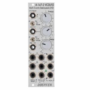
こんな商品も購入されています...
Doepfer A-147-2 Voltage Controlled Delayed Low Frequency Oscillator Module (silver) (envelope generator/LFO/VCA/CV modulation synth module)
Cat: 671585 Rel: 29 Nov 17
Module consisting of voltage-controlled low frequency oscillator (LFO) & voltage controlled amplifier (VCA) - 8HP
Notes: Module A-147-2 is the successor of the VCLFO A-147 but offers much more features than the predecessor. The module is made of these sub-units:
- VCLFO: voltage controlled low frequency oscillator
- VCA: voltage controlled amplifier, switchable to voltage controlled polarizer
- VC delay unit: voltage controlled linear attack envelope (only one parameter: attack) for delayed LFO operation in combination with the VCA (e.g. delayed vibrato/tremolo)
LFO: The voltage controlled LFO has the waveforms Triangle, Sine, Sawtooth and Rectangle available and features a Reset/Sync input. Triangle/Sine and Rectangle are displayed by means of dual-colour LEDs (probably red/green), Sawtooth has a unicolor LED available (probably blue). The output levels are about -4V...+4V for Triangle, Sine and Rectangle. The Sawtooth level is about 0...+8V.
The CV control can be switched to attenuator or polarizer ("CV Mode" switch). In polarizer mode the CV inputs affects the frequency in the reverse manner when the CV control is left from the centre position. In the centre position CV has no effect and right from the centre the control works like a normal attenuator. The frequency range (without external CV) is from about 0,005 Hz (i.e. about 3 minutes per period) to 200 Hz (with external CV max. frequency about 1kHz). In addition a ultra-low mode can be activated by means of an internal jumper. When the ultra-low jumper is set a fixed voltage is connected to the switching contact of the "LFO CV" socket. In polarizer mode of the CV control that way extremely low frequencies (up to one hour period and more) are possible. For this a jumper has to be installed on the pin header JP6. In the factory a dummy jumper is installed on the pin header JP7 "Dummy". JP7 has no function and is used only for "parking" of the jumper. Simply remove the jumper from JP7 and plug it on JP6. JP6 is located behind the CV control.
VCA: This is a linear VCA that can be switched to "normal" VCA (i.e. kind of a voltage controlled attenuator) or voltage controlled polarizer ("VCA Mode" switch). In the "normal" VCA mode amplification +1 is achieved with about +5V control voltage. In polarizer mode the amplification ranges from about -0.5 (i.e. inverted signal with about 50% level) with 0V CV to +0.5 (i.e. non-inverted signal with about 50% level) with +5V CV. With about +2.5V CV the signal is suppressed. Details about the functioning of a voltage controlled polarizer can be found in the description of the module A-133. In this mode the VCA can be treated also a DC coupled ring modulator (similar to A-114).
The VCA of the A-147-2 has three sockets available: "In" (signal input), "Out" (signal output) and "CV" (control voltage input).
The Triangle Output of the LFO is normalled to the VCA signal input by means of the switching contact of the "VCA In" socket. If another LFO waveform (or any other signal) should be processed by the VCA the corresponding signal has to be patched to the "VCA In" socket. The VCA can be used also independently from the LFO and the Delay CV. In this case the VCA sockets In, Out and CV have to be patched accordingly. The VCA can be used also as waveshaper for the LFO signals (e.g. by patching VCA In and VCA CV to different LFO signals, if necessary via attenuator A-183-1 or offset generator/attenuator A-183-2).
Attack/Delay: The third sub-unit of the module is a simple, voltage controlled envelope generator that has only the parameter "Delay" (or Attack) available. This unit generates a linear increasing voltage that starts from 0V after each Delay Reset until it reaches about +5V. Then the voltage remains at +5V until the next Delay Reset occurs. The inclination or gradient is controlled by the manual Delay control and the Delay control voltage ("Delay CV" input). The waveform is linear, the control scale is exponential. The output voltage is displayed by a green LED and available at the "Delay Out" socket.
The manual Delay control ranges - without external "Delay CV" - from about 5ms (fully CW) up to 2 minutes (fully CCW). By means of an external voltage applied to the "Delay CV" socket this range can be extended. A rising CV shortens the delay time (behaviour like a VCO)!
The Delay output voltage ranges from about 0V to +5V. The rising edge of the gate, clock or trigger signal applied to the "Delay Reset" sockets resets the Delay output voltage to 0 V.
"Delay Out" is normalled to the VCA CV input by means of the switching contact of the "VCA CV" socket and consequently controls the Triangle level provided that no other patch is made. A typical example is the usage of a Gate signal (e.g. from a USB/Midi-to-CV/Gate interface) as Delay Reset. That way a delayed vibrato or tremolo can be realized if the VCA output is patched to the frequency CV input of a VCO (or VCF), or the CV input of a VCA.
… Read more- VCLFO: voltage controlled low frequency oscillator
- VCA: voltage controlled amplifier, switchable to voltage controlled polarizer
- VC delay unit: voltage controlled linear attack envelope (only one parameter: attack) for delayed LFO operation in combination with the VCA (e.g. delayed vibrato/tremolo)
LFO: The voltage controlled LFO has the waveforms Triangle, Sine, Sawtooth and Rectangle available and features a Reset/Sync input. Triangle/Sine and Rectangle are displayed by means of dual-colour LEDs (probably red/green), Sawtooth has a unicolor LED available (probably blue). The output levels are about -4V...+4V for Triangle, Sine and Rectangle. The Sawtooth level is about 0...+8V.
The CV control can be switched to attenuator or polarizer ("CV Mode" switch). In polarizer mode the CV inputs affects the frequency in the reverse manner when the CV control is left from the centre position. In the centre position CV has no effect and right from the centre the control works like a normal attenuator. The frequency range (without external CV) is from about 0,005 Hz (i.e. about 3 minutes per period) to 200 Hz (with external CV max. frequency about 1kHz). In addition a ultra-low mode can be activated by means of an internal jumper. When the ultra-low jumper is set a fixed voltage is connected to the switching contact of the "LFO CV" socket. In polarizer mode of the CV control that way extremely low frequencies (up to one hour period and more) are possible. For this a jumper has to be installed on the pin header JP6. In the factory a dummy jumper is installed on the pin header JP7 "Dummy". JP7 has no function and is used only for "parking" of the jumper. Simply remove the jumper from JP7 and plug it on JP6. JP6 is located behind the CV control.
VCA: This is a linear VCA that can be switched to "normal" VCA (i.e. kind of a voltage controlled attenuator) or voltage controlled polarizer ("VCA Mode" switch). In the "normal" VCA mode amplification +1 is achieved with about +5V control voltage. In polarizer mode the amplification ranges from about -0.5 (i.e. inverted signal with about 50% level) with 0V CV to +0.5 (i.e. non-inverted signal with about 50% level) with +5V CV. With about +2.5V CV the signal is suppressed. Details about the functioning of a voltage controlled polarizer can be found in the description of the module A-133. In this mode the VCA can be treated also a DC coupled ring modulator (similar to A-114).
The VCA of the A-147-2 has three sockets available: "In" (signal input), "Out" (signal output) and "CV" (control voltage input).
The Triangle Output of the LFO is normalled to the VCA signal input by means of the switching contact of the "VCA In" socket. If another LFO waveform (or any other signal) should be processed by the VCA the corresponding signal has to be patched to the "VCA In" socket. The VCA can be used also independently from the LFO and the Delay CV. In this case the VCA sockets In, Out and CV have to be patched accordingly. The VCA can be used also as waveshaper for the LFO signals (e.g. by patching VCA In and VCA CV to different LFO signals, if necessary via attenuator A-183-1 or offset generator/attenuator A-183-2).
Attack/Delay: The third sub-unit of the module is a simple, voltage controlled envelope generator that has only the parameter "Delay" (or Attack) available. This unit generates a linear increasing voltage that starts from 0V after each Delay Reset until it reaches about +5V. Then the voltage remains at +5V until the next Delay Reset occurs. The inclination or gradient is controlled by the manual Delay control and the Delay control voltage ("Delay CV" input). The waveform is linear, the control scale is exponential. The output voltage is displayed by a green LED and available at the "Delay Out" socket.
The manual Delay control ranges - without external "Delay CV" - from about 5ms (fully CW) up to 2 minutes (fully CCW). By means of an external voltage applied to the "Delay CV" socket this range can be extended. A rising CV shortens the delay time (behaviour like a VCO)!
The Delay output voltage ranges from about 0V to +5V. The rising edge of the gate, clock or trigger signal applied to the "Delay Reset" sockets resets the Delay output voltage to 0 V.
"Delay Out" is normalled to the VCA CV input by means of the switching contact of the "VCA CV" socket and consequently controls the Triangle level provided that no other patch is made. A typical example is the usage of a Gate signal (e.g. from a USB/Midi-to-CV/Gate interface) as Delay Reset. That way a delayed vibrato or tremolo can be realized if the VCA output is patched to the frequency CV input of a VCO (or VCF), or the CV input of a VCA.
1 in stock $131.52
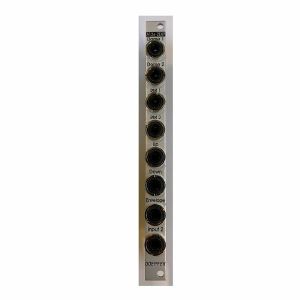
こんな商品も購入されています...
Doepfer A-126-2exp Voltage Controlled Frequency Shifter II - Expansion Module (silver) (expander synth module)
Cat: 852803 Rel: 04 Feb 22
An expander for the A-126-2 Voltage Controlled Frequency Shifter.
Notes: The Doepfer A-126-2exp is an expander for the A-126-2 Voltage Controlled Frequency Shifter.
It adds two outputs from the Dome filter (+45 and -45 degrees) as well as separate outputs from the ring modulators 1 and 2, and from the internal envelope generator. Furthermore, it offers dedicated outputs for Up and Down Shift, allowing the module to be patched in stereo.
*Note: The expander can only be used in conjunction with the module A-126-2.
HP : 2
… Read moreIt adds two outputs from the Dome filter (+45 and -45 degrees) as well as separate outputs from the ring modulators 1 and 2, and from the internal envelope generator. Furthermore, it offers dedicated outputs for Up and Down Shift, allowing the module to be patched in stereo.
*Note: The expander can only be used in conjunction with the module A-126-2.
HP : 2
1 in stock $52.97
Click for better price!
or call +44 20 7424 1960
quote 852803
quote 852803
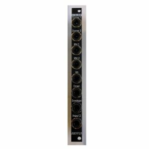
こんな商品も購入されています...
Doepfer A-126-2exp Voltage Controlled Frequency Shifter II - Expansion Vintage Edition Module (black) (expander synth module)
Cat: 852807 Rel: 04 Feb 22
An expander for the A-126-2 Voltage Controlled Frequency Shifter.
Notes: The Doepfer A-126-2exp is an expander for the A-126-2 Voltage Controlled Frequency Shifter.
It adds two outputs from the Dome filter (+45 and -45 degrees) as well as separate outputs from the ring modulators 1 and 2, and from the internal envelope generator. Furthermore, it offers dedicated outputs for Up and Down Shift, allowing the module to be patched in stereo.
*Note: The expander can only be used in conjunction with the module A-126-2.
HP : 2
… Read moreIt adds two outputs from the Dome filter (+45 and -45 degrees) as well as separate outputs from the ring modulators 1 and 2, and from the internal envelope generator. Furthermore, it offers dedicated outputs for Up and Down Shift, allowing the module to be patched in stereo.
*Note: The expander can only be used in conjunction with the module A-126-2.
HP : 2
1 in stock $55.46
Click for better price!
or call +44 20 7424 1960
quote 852807
quote 852807
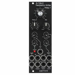
こんな商品も購入されています...
Doepfer A-126-2v Frequency Shifter Module (vintage edition) (sound processor synth module)
Cat: 847083 Rel: 17 Nov 21
Voltage controlled frequency shifter module -
Notes: 'Vintage' black panel version of Doepfer's updated frequency shifter module, offering weird and wonderful effects by shifting all frequencies by a fixed amount. Unique sound, not to be confused with pitch shifting.
Supplier's Notes:
Module A-126-2 is a fully analog frequency shifter for audio signals. A frequency shifter is an audio processing unit that shifts each frequency of the incoming audio signal by the same frequency. If the shifting frequency is e.g. 200Hz an incoming audio frequency of 1000 Hz becomes 1200 Hz, 2000Hz becomes 2200 Hz, 3000 Hz becomes 3200 Hz and so on. Pay attention that this is different from pitch shifting where all frequencies are shifted proportional (e.g. 1000>1200Hz, 2000>2400Hz, 3000>3600Hz) !
The frequency range of the internal quadrature VCO is about 8 octaves (about 20Hz ... 5kHz). If required an external quadrature VCO can be used.
The module is equipped with these controls, inputs and outputs:
Frequ. 1: first manual control of the shifting frequency (factory setting: coarse, range about 20Hz - 5 kHz)
Frequ. 2: second manual control of the shifting frequency (factory setting: fine)
by means of internal jumpers the sensitivity of Frequ.1 and 2 can be swapped (i.e. Frequ.1 = fine and Frequ.2 = coarse)
the relation between coarse and fine control is about 25:1 (corresponding to about 8 octaves to 1/3 octave)
FCV In (socket) and FCV (small control without knob): control voltage input with attenuator for the external voltage control of the shifting frequency
Mix: manual control of the up/down shift panning unit, fully CCW = down shift, fully CW = up shift, in between a mixture of down and up
Mix CV In (socket) and Mix CV (small control without knob): control voltage input with attenuator for the mixing unit for external voltage control of the up/down mixing
Audio In (socket), Level (small control without knob) and Overload (LED): audio input with attenuator, typ. audio in level = 1Vpp, the level control has to be adjusted so that the overload LED just begins to light up a bit, when the LED is fully on clipping/distortion occurs, when the LED is permanently off the input level is too low and the signal-to-noise ratio increases
Audio Out (socket): audio output of the frequency shifter
Squelch (small control without knob): controls the squelch function: fully CCW (Env.) the output VCA is controlled by the envelope signal, which is derived from the audio input signal, fully CW (open) the output VCA is permanently open (no squelch function), in between the squelch intensity can be adjusted
Quadrature VCO Outputs (sockets Sin and Cos): outputs of the internal quadrature oscillator, about 12Vpp level (+6V/-6V)
Ext. Inputs Sin and Cos (sockets): required when an external quadrature VCO (e.g. A-143-9 with a wider frequency range or A-110-4 with thru zero feature or A-110-6 with different waveforms) is used instead of the internal quadrature VCO, the levels of the external VCO should be about 10Vpp (8...10Vpp are OK) and the signals have to be symmetrical around zero Volts, the sockets are normalled to the internal quadrature VCO (i.e. the sockets are equipped with switching contacts that interrupt the internal connection as soon as a plug inserted)
VCA ext. CV (socket): used when an external control voltage (e.g. from an envelope generator) should be used to control the output VCA instead of the internal squelch unit, the socket is normalled to the output of the squelch control (i.e. the socket is equipped with a switching contact that interrupts the internal squelch connection as soon as a plug inserted). From about +8V external control voltage the VCA is fully open.
Internal terminals (pin headers, e.g. for a DIY breakout module):
envelope follower output
dome filter output 1
dome filter output 2
ring modulator 1 output
ring modulator 2 output
Up shift output
Down shift output
… Read moreSupplier's Notes:
Module A-126-2 is a fully analog frequency shifter for audio signals. A frequency shifter is an audio processing unit that shifts each frequency of the incoming audio signal by the same frequency. If the shifting frequency is e.g. 200Hz an incoming audio frequency of 1000 Hz becomes 1200 Hz, 2000Hz becomes 2200 Hz, 3000 Hz becomes 3200 Hz and so on. Pay attention that this is different from pitch shifting where all frequencies are shifted proportional (e.g. 1000>1200Hz, 2000>2400Hz, 3000>3600Hz) !
The frequency range of the internal quadrature VCO is about 8 octaves (about 20Hz ... 5kHz). If required an external quadrature VCO can be used.
The module is equipped with these controls, inputs and outputs:
Frequ. 1: first manual control of the shifting frequency (factory setting: coarse, range about 20Hz - 5 kHz)
Frequ. 2: second manual control of the shifting frequency (factory setting: fine)
by means of internal jumpers the sensitivity of Frequ.1 and 2 can be swapped (i.e. Frequ.1 = fine and Frequ.2 = coarse)
the relation between coarse and fine control is about 25:1 (corresponding to about 8 octaves to 1/3 octave)
FCV In (socket) and FCV (small control without knob): control voltage input with attenuator for the external voltage control of the shifting frequency
Mix: manual control of the up/down shift panning unit, fully CCW = down shift, fully CW = up shift, in between a mixture of down and up
Mix CV In (socket) and Mix CV (small control without knob): control voltage input with attenuator for the mixing unit for external voltage control of the up/down mixing
Audio In (socket), Level (small control without knob) and Overload (LED): audio input with attenuator, typ. audio in level = 1Vpp, the level control has to be adjusted so that the overload LED just begins to light up a bit, when the LED is fully on clipping/distortion occurs, when the LED is permanently off the input level is too low and the signal-to-noise ratio increases
Audio Out (socket): audio output of the frequency shifter
Squelch (small control without knob): controls the squelch function: fully CCW (Env.) the output VCA is controlled by the envelope signal, which is derived from the audio input signal, fully CW (open) the output VCA is permanently open (no squelch function), in between the squelch intensity can be adjusted
Quadrature VCO Outputs (sockets Sin and Cos): outputs of the internal quadrature oscillator, about 12Vpp level (+6V/-6V)
Ext. Inputs Sin and Cos (sockets): required when an external quadrature VCO (e.g. A-143-9 with a wider frequency range or A-110-4 with thru zero feature or A-110-6 with different waveforms) is used instead of the internal quadrature VCO, the levels of the external VCO should be about 10Vpp (8...10Vpp are OK) and the signals have to be symmetrical around zero Volts, the sockets are normalled to the internal quadrature VCO (i.e. the sockets are equipped with switching contacts that interrupt the internal connection as soon as a plug inserted)
VCA ext. CV (socket): used when an external control voltage (e.g. from an envelope generator) should be used to control the output VCA instead of the internal squelch unit, the socket is normalled to the output of the squelch control (i.e. the socket is equipped with a switching contact that interrupts the internal squelch connection as soon as a plug inserted). From about +8V external control voltage the VCA is fully open.
Internal terminals (pin headers, e.g. for a DIY breakout module):
envelope follower output
dome filter output 1
dome filter output 2
ring modulator 1 output
ring modulator 2 output
Up shift output
Down shift output
1 in stock $335.77
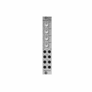
こんな商品も購入されています...
Doepfer A-183-5 Quad Attenuator Slim Line Series Module (silver) (attenuator/quad synth module)
Cat: 880264 Rel: 05 Oct 22
Module A-183-5 is a simple passive quad attenuator.
Notes: Module A-183-5 is a simple passive quad attenuator. Passive means in this context, that each unit is made of two sockets and a 50k linear potentiometer only. There are no active parts like amplifiers or buffers and no power supply is required.
This is how the A-183-5 works: At the output socket appears the attenuated input signal, i.e. zero level at the fully CCW position and max. level and the fully CW position.
Applications:
Adjustable level of CV or audio signals to control other modules that do not have attenuators available.
Dimensions
4 HP
20 mm deep
… Read moreThis is how the A-183-5 works: At the output socket appears the attenuated input signal, i.e. zero level at the fully CCW position and max. level and the fully CW position.
Applications:
Adjustable level of CV or audio signals to control other modules that do not have attenuators available.
Dimensions
4 HP
20 mm deep
1 in stock $65.45
Click for better price!
or call +44 20 7424 1960
quote 880264
quote 880264
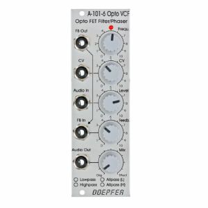
こんな商品も購入されています...
Doepfer A-101-6 6-Stage VC Opto-FET Filter & Phaser Module (silver) (filter/phase shifter/effect synth module)
Cat: 682323 Rel: 26 Mar 18
6-stage VC Opto-FET filter/phaser - 8HP
Notes: A-101-6 is a new filter module that uses so-called opto FET's to control the filter frequency. Opto FET's are very similar to Vactrols, but use light dependent field effect transistors (FET's) instead of light dependent resistors (LDR's). An opto FET is a combination of a light-dependent FET and an LED, both put into a small light-proof case. The advantage, compared to vactrols, is a much faster response of opto FET's compared to LDR's - this allows much faster attack/decay times and even FM effects.
The variable resistors corresponds to the opto FET. The brightness of the Opto FET LED's, and consequently the filter frequency, can be adjusted manually (Frequ. control) and controlled by means of an external control voltage (CV) with attenuator. The LED at the front panel reflects the LED brightness inside the opto FET's.
The type of filter is chosen by jumpers on the PC board (factory setting: low pass). The type of filter determined by the jumpers positions can be marked by means of a water-resistant felt pen at the front panel.
The resonance is controlled by the Feedback control up to self-oscillation. By means of a trimming potentiometer the maximal feedback can be adjusted. High feedback values can be used mainly in the all-pass mode to obtain very extreme self-oscillation sounds. Even an external feedback signal can be used instead of the internal feedback connection (FB In socket). Whenever the filter type is changed by means of the jumpers the trimming potentiometer for the maximal feedback has to be re-adjusted.
The Mix control is used to pan between the original signal (CCW position) and the effect signal (CW position). In filter mode (LP/HP) this control is usually set fully CW. In the all-pass modes one obtains phasing sounds at centre position or "pure" all-pass sound in fully CW position.
… Read moreThe variable resistors corresponds to the opto FET. The brightness of the Opto FET LED's, and consequently the filter frequency, can be adjusted manually (Frequ. control) and controlled by means of an external control voltage (CV) with attenuator. The LED at the front panel reflects the LED brightness inside the opto FET's.
The type of filter is chosen by jumpers on the PC board (factory setting: low pass). The type of filter determined by the jumpers positions can be marked by means of a water-resistant felt pen at the front panel.
The resonance is controlled by the Feedback control up to self-oscillation. By means of a trimming potentiometer the maximal feedback can be adjusted. High feedback values can be used mainly in the all-pass mode to obtain very extreme self-oscillation sounds. Even an external feedback signal can be used instead of the internal feedback connection (FB In socket). Whenever the filter type is changed by means of the jumpers the trimming potentiometer for the maximal feedback has to be re-adjusted.
The Mix control is used to pan between the original signal (CCW position) and the effect signal (CW position). In filter mode (LP/HP) this control is usually set fully CW. In the all-pass modes one obtains phasing sounds at centre position or "pure" all-pass sound in fully CW position.
1 in stock $107.61
Click for better price!
or call +44 20 7424 1960
quote 682323
quote 682323
